Delidded my GTX460...[update 9/18] results are in!

Status
Not open for further replies.

Idontcare

Elite Member
Oct 10, 1999
21,118
58
91
So I was busy lapping my H100 and 2600K and I glanced over at my setup and my MSI GTX460 Cyclone (stock OC 725MHz) caught my eye...

Long ago I replaced the stock cyclone HSF with an Artic Cooling Accelero XTREME Plus. At the time I was mildly curious if I should lap the HSF surface as well as the IHS of the GPU, but I didn't do it then.

Not so anymore. I pulled off the Accelero Extreme HSF thinking I would figure out a way to lap that GTX460 IHS now.

DSCN0519.jpg


Notice those aluminum heatspreaders sitting on the vrm's on 3 sides of the GPU...those are adhesive glued onto the vrm's and they aren't coming off so that I could get in that area to lap the IHS directly.

So then I started thinking about the next alternative...why not just pop the lid off the GTX460 altogether? I could lap it freehand and then reattach it to the GPU, or just go bare-silicon if I can figure out a way to avoid cracking the exposed chip.

To pop the lid off the GPU, it was surprising easy, I used a standard razor blade:
042810025644_RAZOR1.jpg


I forcefully inserted it into one corner of the IHS interface with the GPU's PCB, then I tapped on it with a very small carpenter's hammer until it penetrated the corner by about 3/16". (sorry no pics with the razor stuck in the IHS, the lid came off before I could stage it for a photo)

DSCN0520.jpg


I did one corner, then the other corner (same side, since I did not have a good angle of entry for the other two corners owing to the vrm heatsinks)...and "pop" it just came off in a matter of seconds with some slight prying of the blade.

I'll be honest, I had my eyes closed at the time because I didn't have my safety glasses on (I'm actually quite paranoid about that) and I did not want the blade itself to shatter and throw shards into my eyes.

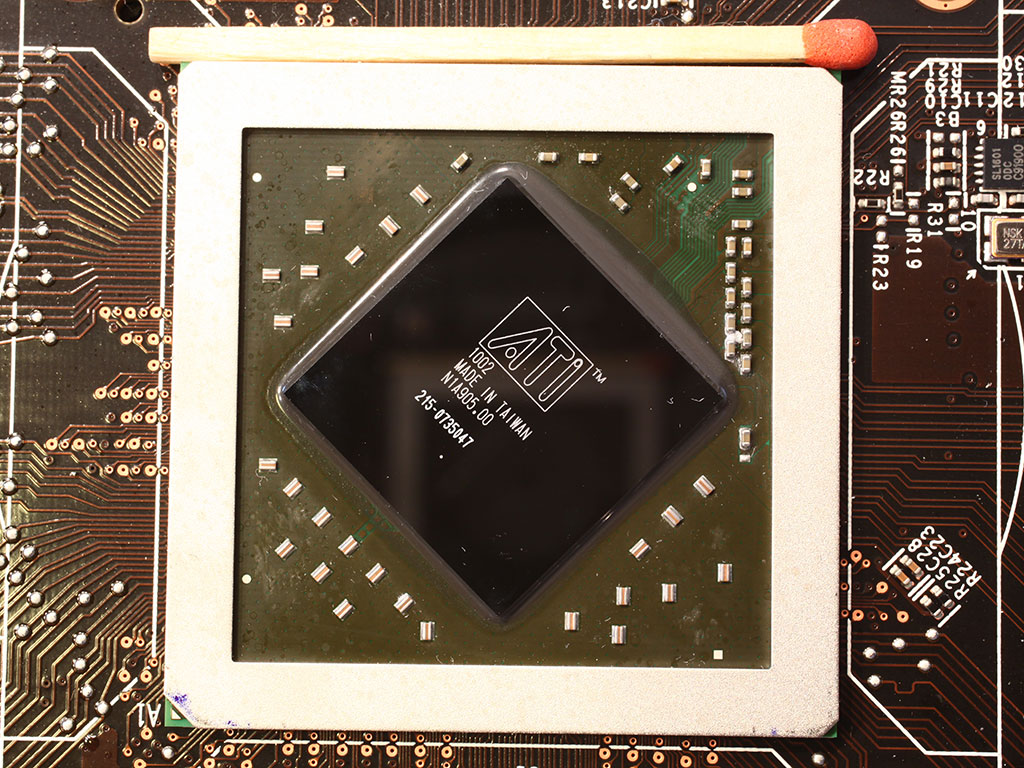
Nevertheless it popped off and I was left with:
DSCN0521.jpg


As luck would have it, I managed to avoid shearing off the capacitors that surround the perimeter of the GPU chip itself when I was tapping the blade into the interface below the IHS.

DSCN0522.jpg


That gray stuff you see on top of the GPU chip and on the inside surface of the IHS is just regular TIM, its not soldered to the IHS at all.

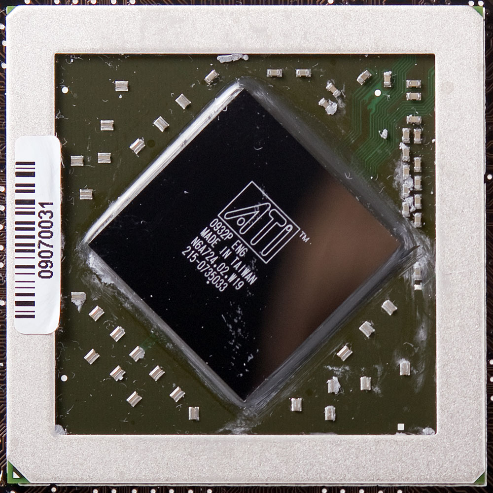
Cleaned up with some 91% IPA and standard kitchen paper towels:
DSCN0528.jpg


I was rather surprised how porous and rough the internal surface of the IHS is, no wonder they had to add liberal amounts of TIM to that interface:
DSCN0541.jpg


Now that the lid is off I am posed with a new challenge, the Accelero Extreme HSF has stand-offs built into the mounting bracket. The stand-offs of course are designed to accommodate the relatively thick IHS cap of the GTX460.

DSCN0543.jpg


DSCN0545.jpg


So my choices are: (1) lap the IHS and reseat it back onto the GPU chip, or (2) cut down the HSF stand-offs and attempt to place the HSF's copper surface directly onto the GPU silicon.

Option (2) is clearly the highest-risk highest-reward option. I'd really like to not crack the chip and kill the GPU. On the other hand I'm immensely curious to see just how much lower the temps will be with that ghastly IHS block NOT standing in the way of the heat transfer to the HSF.

So what does the VC&G community have to say? Anyone here have experience with delidded chips? (I missed all that fun back with delidding AMD chips before they started soldering them on permanent-like) Got any advice on how much or how little pressure I can apply to the chip before it goes poof?


edit: results are in, see post 38, 10C decrease in temps with OCCT.
 
Last edited:

Bartman39

Elite Member | For Sale/Trade
Jul 4, 2000
8,878
51
91
Just a thought but you could find either washers or small nuts the thickness of the IHS and place them on the standoffs then use a drill that is about 3 times the size of the standoff and basicly mill it down till the washer or nut spins to get a uniform thickness on all standoff's... Then I would get longer screws and springs that fit the screws and mount the HS with these and adjust the tension rather careful... Or with the springs and longer screws you might not even need to mill the standoff's...?

Just think back to the old XP cpu days way before IHS chips we put a lot of pressure on those babies back then and only had a single spring clip to attach them... Sure several were killed by cracking off a corner here and there but it took a real gorilla to do this but a steady hand and a little attention and I never killed one...:thumbsup:
 

Elfear

Diamond Member
May 30, 2004
7,097
644
126
Go naked or go home!

Seriously though, I'd go for option 2. If the card can handle some volts, it should make for some uber overclocking on air.
 

hdfxst

Senior member
May 13, 2009
851
3
81
The stand offs on the accelero s1 look like plastic tubing and i was thinking you could get tubing to go over the standoff and extend it.the tubing would crush and not put all the pressure on the core
 

BD231

Lifer
Feb 26, 2001
10,568
138
106
It's the rest of the components that limit the overclocks on these cards TBH, to late now I guess. Buy another one :D
 

Idontcare

Elite Member
Oct 10, 1999
21,118
58
91
It's the rest of the components that limit the overclocks on these cards TBH, to late now I guess. Buy another one :D
Already have another one, but was hoping to put them in SLI versus one being the backup to the other.

But I'm more curious about temps, if I get more OC out of it because of the improved thermal headroom then all the better.

Just a thought but you could find either washers or small nuts the thickness of the IHS and place them on the standoffs then use a drill that is about 3 times the size of the standoff and basicly mill it down till the washer or nut spins to get a uniform thickness on all standoff's... Then I would get longer screws and springs that fit the screws and mount the HS with these and adjust the tension rather careful... Or with the springs and longer screws you might not even need to mill the standoff's...?

Just think back to the old XP cpu days way before IHS chips we put a lot of pressure on those babies back then and only had a single spring clip to attach them... Sure several were killed by cracking off a corner here and there but it took a real gorilla to do this but a steady hand and a little attention and I never killed one...:thumbsup:

Yeah I was thinking of just marking each standoff at the height of the IHS's thickness (from the bottom of the standoff, not the top, of course) and using the dremel with a metal cutter blade, followed by a nice 60/220 grit polish to level all four of the posts.

I do like the suggestion of cutting them a skosh shorter than that but to then jacket the posts with springs to provide a more cushioned landing on the GPU chip.
 

superccs

Senior member
Dec 29, 2004
999
0
0
Nice photos and fun project... I think every one on here has a 460 to play with and is interested on naked option. Every one probably has an accelero too. By everyone I mean me 8)
 

bryanW1995

Lifer
May 22, 2007
11,144
32
91
Oh man, that looks like fun. I think I'll wait until next gen is out before going naked, though.
 
Mar 11, 2004
23,076
5,557
146
Already have another one, but was hoping to put them in SLI versus one being the backup to the other.

But I'm more curious about temps, if I get more OC out of it because of the improved thermal headroom then all the better.


Yeah I was thinking of just marking each standoff at the height of the IHS's thickness (from the bottom of the standoff, not the top, of course) and using the dremel with a metal cutter blade, followed by a nice 60/220 grit polish to level all four of the posts.

I do like the suggestion of cutting them a skosh shorter than that but to then jacket the posts with springs to provide a more cushioned landing on the GPU chip.

This is perfect of running them in SLI though, as one card tends to get quite a bit hotter when doing that, so this will help counteract that.
 

OVerLoRDI

Diamond Member
Jan 22, 2006
5,494
4
81
I'd love to see the you do option 2, you could start a silly trend of delidding Nvidia GPUs ;) Also 460s aren't exactly expensive (depending on how much $ you make/have)

I'd also like to see your results of lapping your 2600k and H100 (might consider lapping my 2500k, my Apogee XT block is beautiful, doesn't really need any lapping)
 

ZimZum

Golden Member
Aug 2, 2001
1,281
0
76
Every time Ive tried to do this with a CPU I've ended up with a key-chain. Stupid, chubby fingers!!
 

Idontcare

Elite Member
Oct 10, 1999
21,118
58
91
All right, you guys convinced me, in the name of science of course, to keep the lid off and put in some effort to get the cooler onto the naked silicon without cracking it :)

I'll keep you all updated. It'll be a few days though as my desktop is completely down with my ram under rma at the moment.
 

SlowSpyder

Lifer
Jan 12, 2005
17,305
1,001
126
Do you have a Dremel? I imagine ACE Hardware, or someplace similar, will have a tap you can run through to clean up the threads after cutting down the size of those stand-offs with a Dremel. Of course, buying a tap and possibly a Dremel probably starts to make the project not worth it from a cost standpoint. But, then again, a hobby is typically all about wasting money. ;)

$10-$60 for another 35MHz and 4C... gotta love PC enthusiasts. ;)
 

Idontcare

Elite Member
Oct 10, 1999
21,118
58
91
Yeah I already have a dremel, and the metal blades and sanding wheels. So no more out-of-pocket there.

As for the threads, I can't imagine I'll ah heck up the existing threads to the point that the screws themselves won't be sufficient to re-thread the entry turn. I could be wrong but I'll cross that bridge when I get there. There's always JB Weld :D
 

SlowSpyder

Lifer
Jan 12, 2005
17,305
1,001
126
Yeah I already have a dremel, and the metal blades and sanding wheels. So no more out-of-pocket there.

As for the threads, I can't imagine I'll ah heck up the existing threads to the point that the screws themselves won't be sufficient to re-thread the entry turn. I could be wrong but I'll cross that bridge when I get there. There's always JB Weld :D


I have a buddy that used JB Weld on a crack in the engine block of his car. So, I think it'll be just fine for the stresses of a video card cooler. ;) And of course if that doesn't work, there is always zip ties.

MSI Cyclone Ghettofied Edition. ;)
 

nitromullet

Diamond Member
Jan 7, 2004
9,031
36
91
Have you tried just putting the HSF back on as it is? That cooler is compatible with a number of AMD cards that don't have heat spreaders, so it's possible it might work as is. There is height restriction drawing on Arctic Cooling's site that indicates the gap between PCB and the base of the HSF is 3.30mm.

http://www.arctic.ac/en/p/detail?sArticle=18.%3F
 

KingFatty

Diamond Member
Dec 29, 2010
3,034
1
81
Yeah I already have a dremel, and the metal blades and sanding wheels. So no more out-of-pocket there.

As for the threads, I can't imagine I'll ah heck up the existing threads to the point that the screws themselves won't be sufficient to re-thread the entry turn. I could be wrong but I'll cross that bridge when I get there. There's always JB Weld :D

If you need a tap, you can always use a spare screw, and "sharpen" the end of that screw slightly using the dremel (grinder bit), then cut a couple notches parallel to the screw axis using a cutter wheel. Worked well for me, and you can get creative and make it look just like a tap depending how you cut the notches and the amount of overall sharpening of the screw.
 

Idontcare

Elite Member
Oct 10, 1999
21,118
58
91
Have you tried just putting the HSF back on as it is?

Yes I have, there's a gap between the HSF Cu plate and the GPU silicon chip of about 2-3 mm.

The Accelero uses different plates for the differing GPU's. Just like CPU HSF's use different backplates depending on the socket (AM2, LGA775, etc).
 

Idontcare

Elite Member
Oct 10, 1999
21,118
58
91
If you need a tap, you can always use a spare screw, and "sharpen" the end of that screw slightly using the dremel (grinder bit), then cut a couple notches parallel to the screw axis using a cutter wheel. Worked well for me, and you can get creative and make it look just like a tap depending how you cut the notches and the amount of overall sharpening of the screw.

Excellent tip :thumbsup: I'll do this if it turns out that I need to re-tap the threads. Thanks for sharing it!
 

Patrick Wolf

Platinum Member
Jan 5, 2005
2,443
0
0
I think those bare chips are fairly durable, or at least ATI thought so anyway. The 5770 I re-TIMed had no IHS (though it was maybe 1/3 the size of that 460 chip).
 

notty22

Diamond Member
Jan 1, 2010
3,375
0
0
I might be wrong, but one thing I notice is that AMD gpu's seem to have a clear wax like substance over the small electronics around the die. The things pointed to by the yellow arrow.

Here is a Cayman gpu without the heatsink.
The substance is definitely around the gpu die.
I would think you want to keep all tim off of them. And I guess you could manage that, since the interanl heat spreader did use tim.
gpu.jpg

die.jpg
 
Last edited:
Status
Not open for further replies.