Edit: Adding direct links to specific posts within this thread that contain specific updates, a table of contents if you will:
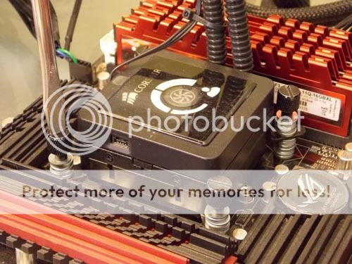
I happen to have a collection of thermal pastes that I figured would make for some fun testing with bare-die mounting (no IHS) on a delidded i7-3770K.

~$200 worth of assorted TIMs :whiste: Let's see if we can put them to good use
The tests here are all conducted with an H100 (4 fans in push-pull, lapped to 3000 grit) on an Asus MIVE-Z.

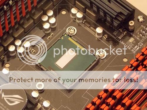
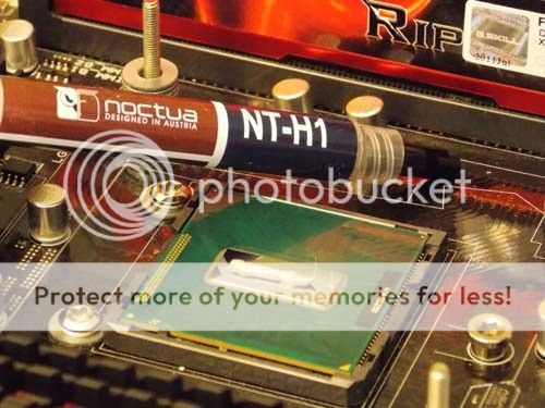
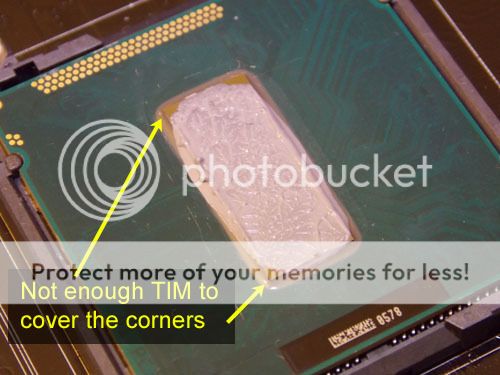
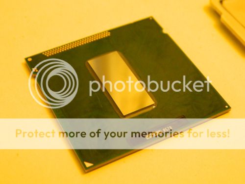
I've already removed the IHS from the 3770k, and the bare die is fully exposed (technically we are looking at the backside of the die, the cpu sits upside down with the frontside soldered to the green PCB).
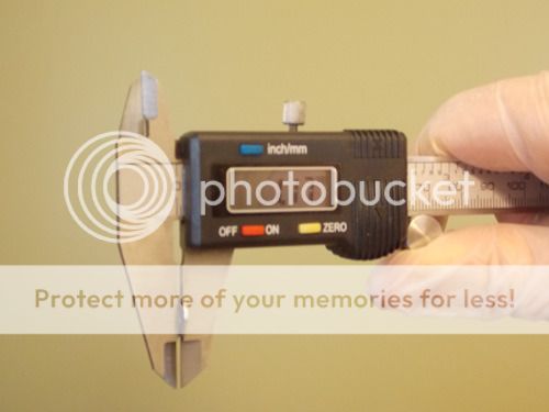
If we attempted to mount the H100 to the bare-die 3770k at this point the socket's retention bracket would get in the way because the bracket hardware sticks up higher than the cpu die itself (normally the IHS pokes up higher than the retention bracket so this isn't an issue).
If we left the socket's retention bracket in place with our lidless 3770k the HSF would not be able to contact the CPU and that would be bad for temperatures
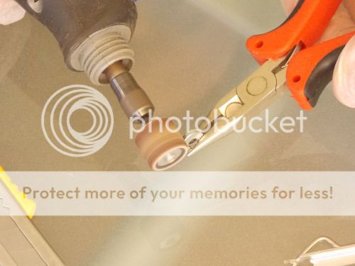
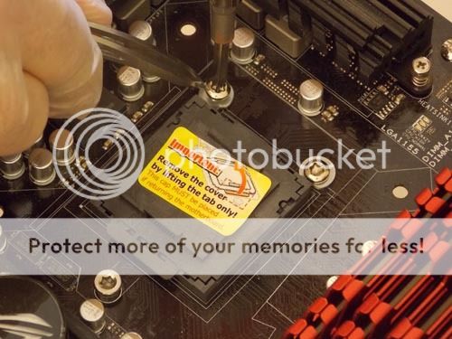
So the next step here is to remove the socket's retention bracket hardware. It might sound like a daunting task but it really is quite simple to accomplish. There are three bolts which use a standard star-key bit available in most $5 bit-kits you would get at Home Depot.

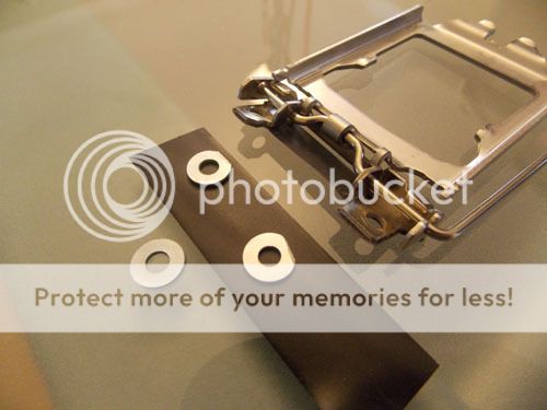
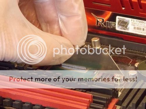
Retention bracket successfully removed

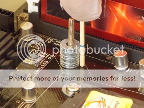
We aren't close to being ready to start our tests though, we need to prepare the socket for test as well as deal with the H100 mounting bracket itself which is now set to the wrong height owing to the now missing IHS.
- Bare-die testing: A delidded 3770k, an H100, and 9 different TIMs (that's this post, read below )
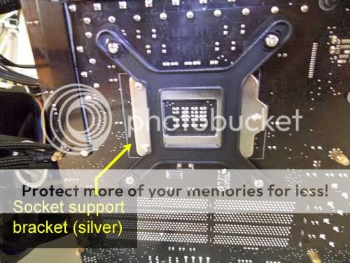
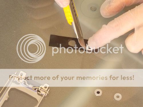
- Socket Preparation - Preserving the Backside Socket Support Bracket
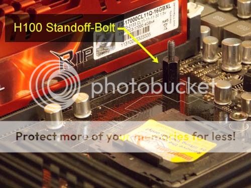
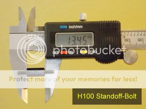
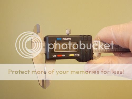
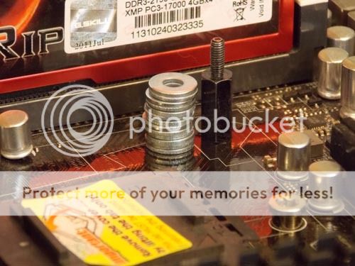
- Crafting a robust replacement for the H100 mounting bracket
- Final prep work on the H100 mounting bracket
- Results with MX-4
- Results with IC Perihelion
- Results with Céramique
- Results with AS5 (Arctic Silver 5)
- Results with Tuniq TX-1
- Results with Tuniq TX-2
- Results with IC Diamond
- Results with NT-H1 (Noctua)
- Results with Liquid Ultra (Part 1 of 2)
- Results with Liquid Ultra (Part 2 of 2)
- Results with NT-H1 (the silly, way-too-much, test)
- Results Summary
I happen to have a collection of thermal pastes that I figured would make for some fun testing with bare-die mounting (no IHS) on a delidded i7-3770K.
~$200 worth of assorted TIMs :whiste: Let's see if we can put them to good use
The tests here are all conducted with an H100 (4 fans in push-pull, lapped to 3000 grit) on an Asus MIVE-Z.
I've already removed the IHS from the 3770k, and the bare die is fully exposed (technically we are looking at the backside of the die, the cpu sits upside down with the frontside soldered to the green PCB).
If we attempted to mount the H100 to the bare-die 3770k at this point the socket's retention bracket would get in the way because the bracket hardware sticks up higher than the cpu die itself (normally the IHS pokes up higher than the retention bracket so this isn't an issue).
If we left the socket's retention bracket in place with our lidless 3770k the HSF would not be able to contact the CPU and that would be bad for temperatures
So the next step here is to remove the socket's retention bracket hardware. It might sound like a daunting task but it really is quite simple to accomplish. There are three bolts which use a standard star-key bit available in most $5 bit-kits you would get at Home Depot.
Retention bracket successfully removed
We aren't close to being ready to start our tests though, we need to prepare the socket for test as well as deal with the H100 mounting bracket itself which is now set to the wrong height owing to the now missing IHS.
Last edited: