-
We’re currently investigating an issue related to the forum theme and styling that is impacting page layout and visual formatting. The problem has been identified, and we are actively working on a resolution. There is no impact to user data or functionality, this is strictly a front-end display issue. We’ll post an update once the fix has been deployed. Thanks for your patience while we get this sorted.
You are using an out of date browser. It may not display this or other websites correctly.
You should upgrade or use an alternative browser.
You should upgrade or use an alternative browser.
Bare-die testing: A delidded 3770k, an H100, and 9 different TIMs
Page 2 - Seeking answers? Join the AnandTech community: where nearly half-a-million members share solutions and discuss the latest tech.
Sunny129
Diamond Member
my guess is that he's using washers b/c they're non-compressible, unlike a spring. with springs, you'd have to rely much more heavily on "feel" to make sure you don't over-tighten the heatsink and accidentally crush the de-lidded and now-unprotected die. w/ the washers, you can tighten it it to your heart's desire, and the screws will stop turning before the die gets crushed b/c the washers aren't compressible.Thanks, I missed that paragraph.
^ I'm inclined to believe compression with springs probably *won't* give less repeatability than bolting on directly though, so long as you repeat your mounting method and don't switch which spring goes in which corner between mounts. At least with springs you have a good idea of how many N/m² you're putting on if you know the spring rate.
Yuriman
Diamond Member
To each his own.
Anyhow, I have my 1-month results with CL Ultra used on a bare die mount posted in your delidding thread, IDC:
http://forums.anandtech.com/showthread.php?p=34290850#post34290850
Anyhow, I have my 1-month results with CL Ultra used on a bare die mount posted in your delidding thread, IDC:
http://forums.anandtech.com/showthread.php?p=34290850#post34290850
EliteRetard
Diamond Member
... The IHS itself measures right near 3mm:

...don't forget that this includes the perimeter lip of the IHS, it doesn't capture the fact that the inside surface of the IHS form a cavity that sits on top of the CPU die itself (which we must also remember does not sit flush with the surface of the PCB either).
Putting a 1mm thick washer inside the IHS cavity and measuring it again shows us the cavity depth:

Basically we need our replacement standoffs to be 2 washers (2mm) shorter than the stock H100 standoff bolt.
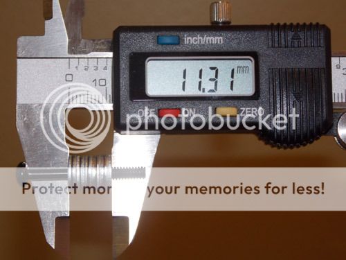
Bingo! That will work quite nicely as a substitute stand-off bolt while accounting for the absence of the IHS 🙂
For some reason I can't get my brain to do the math. Subtracting the 1mm washer from the cavity depth suggests the IHS is about .4mm thick.
2.98mm - (3.59mm - 1mm) = .39mm
If the heatsink was snug on the IHS before, shouldn't you just be reducing the height by the thickness of the IHS? In this case 1x1mm washer should be more than enough. Where are you getting the 2mm number from? Obviously you didn't crush the die, so I must be missing something...or perhaps I am right and it just happened to be fine with the extra pressure?
Last edited:
For some reason I can't get my brain to do the math. Subtracting the 1mm washer from the cavity depth suggests the IHS is about .4mm thick. (2.98mm - 2.59mm)
If the heatsink was snug on the IHS before, shouldn't you just be reducing the height by the thickness of the IHS? In this case 1x1mm washer should be more than enough. Where are you getting the 2mm number from? Obviously you didn't crush the die, so I must be missing something...or perhaps I am right and it just happened to be fine with the extra pressure?
The die stick upwards into the IHS cavity by ~0.5mm, the IHS doesn't actually sit on the PCB, it sits on the die. So by removing the IHS I am really only reducing the total stack height by the thickness of the IHS from the inside, not counting its perimeter.

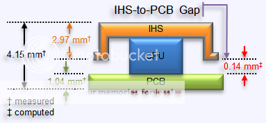
4.15 - 1.57 = 2.58mm
(the computed thickness of the IHS cap from the inside of the cavity to the surface, not including the flange)
For a more in-depth analysis see this post and this post.
So, by removing the IHS we have reduced the stack height by ~2.6mm. If I remove 2 washers then the stack height will be ~0.6mm higher relative to I removed the IHS when using the old offset.
We don't want to create a new gap by having too many washers in place, so I have a choice of removing one washer and creating a gap of 0.4mm (will yield very poor thermals) or I can remove two washers and have the H100 sitting directly on the die, just as we like, with the remaining 0.6mm space providing the net-positive mounting pressure down on the socket.
While I don't know if that is enough of a gap to create enough down-pressure as to suitably replace the down-pressure created by the stock H100 stand-off bolts, that isn't what I was going for here. What I wanted was repeatable mounting to ensure the TIMs were being evaluated in as close to an apples-to-apples fashion as possible.
Provided the down-pressure is within the ballpark of being reasonable and getting the job done, of course. That is also why I opted to not go with the springs. I would have no control over the resulting down-force between any two mounting efforts. Being able to turn the screws to full stop pretty much ensures repeatability because the full-stop point isn't going to change between mounts.
(that and the fact that Corsair went with fixed-height standoffs instead of springs tells me there must be some good reason why the springs are not used with this particular water-block)
Yuriman
Diamond Member
Bolt-on mounting without springs was almost unheard of in the days of bare dies when balanced pressure was important, I always thought it was a cost saving measure to leave the springs out in kits for CPUs with heatspreaders. I trust your ability to collect good data though. Bring on the tables. 😀
Last edited:
EliteRetard
Diamond Member
DERP! I did do my math wrong, the lip is ~.4mm while the thickness of the IHS is ~2.6mm for a total thickness of about 3mm.
That lines up with your math...I simply confused the lip and thickness numbers.
But this paragraph you just wrote is a bit confusing/wrong:
"We don't want to create a new gap by having too many washers in place, so I have a choice of removing one washer and creating a gap of 0.4mm (will yield very poor thermals) or I can remove two washers and have the H100 sitting directly on the die, just as we like, with the remaining 0.6mm space providing the net-positive mounting pressure down on the socket."
If you had removed a single washer the gap between the heatsink and the die would be ~1.6mm (not the .4mm you said) while taking away 2 should leave a gap of ~.6mm. Probably just a typo, since if you took out 3 you would be crushing the die by ~.4mm.
I understand what you did and why for the testing, makes sense to me.
For a permanent setup you could shave down a set of washers (or buff them all a little), to reduce the gap (considering the stock paste under the IHS added less than a .1mm gap). I know you just love sanding 😀
So your total stack on each post would measure a nice even 11mm and give you less paste between the die and heatsink (I'm figuring you'll be right around 1mm gap then). Should give you even better temperatures, and that seems to be the goal 🙂
Bolt-on mounting without springs was almost unheard of in the days of bare dies when balanced pressure was important, I always thought it was a cost saving measure to leave the springs out in kits for CPUs with heatspreaders. I trust your ability to collect good data though. Bring on the tables. 😀
The H100 may not use springs in the standoffs but it uses a spring-like bracket effect anyways.
The flanges on the block itself are thin metal extensions which notably flex as you turn the thumb-nuts to full stop. It is the metal flanges that provide the even downforce on all four corners of the H100.
That effect is still in play here. Without that flex in the system the die itself would surely be crushed from the downforce.
Originally I was intending for this washer-substitute to just be a test setup that I would replace with springs once I was ready to setup the 3770k for permanent personal usage, but I've grown so comfortable with the washer stand-offs and the repeatable mounting experience that I'm probably just going to keep it now. It has gained my confidence whereas before I was suspicious of the approach.
DERP! I did do my math wrong, the lip is ~.4mm while the thickness of the IHS is ~2.6mm for a total thickness of about 3mm.
That lines up with your math...I simply confused the lip and thickness numbers.
But this paragraph you just wrote is a bit confusing/wrong:
"We don't want to create a new gap by having too many washers in place, so I have a choice of removing one washer and creating a gap of 0.4mm (will yield very poor thermals) or I can remove two washers and have the H100 sitting directly on the die, just as we like, with the remaining 0.6mm space providing the net-positive mounting pressure down on the socket."
If you had removed a single washer the gap between the heatsink and the die would be ~1.6mm (not the .4mm you said) while taking away 2 should leave a gap of ~.6mm. Probably just a typo, since if you took out 3 you would be crushing the die by ~.4mm.
I understand what you did and why for the testing, makes sense to me.
For a permanent setup you could shave down a set of washers (or buff them all a little), to reduce the gap (considering the stock paste under the IHS added less than a .1mm gap). I know you just love sanding 😀
So your total stack on each post would measure a nice even 11mm and give you less paste between the die and heatsink (I'm figuring you'll be right around 1mm gap then). Should give you even better temperatures, and that seems to be the goal 🙂
Yep, you're right, I've increased the relative gap by 0.6mm. What I don't know is how much of a gap I had to begin with from the perspective of the H100.
I know when I set the H100 on top of the IHS, when using the stock stand-off bolts, the gap between the top of the stand-off bolts and the H100 flange is a good 2mm. That 2mm gap is closed down to zero once the thumb-nuts are turned to full-stop, flexing the H100 metal flange arms down by 2mm deflection which then provides the downforce on the H100 to the IHS.
So, even though I didn't reduce the stack height by the same amount as the IHS, it is still a net negative gap such that when I torque down those thumb-nuts the H100 metal flange (whatever they are called, tabs, arms, whatever) the H100 is definitely applying solid down-pressure on the CPU die as the resultant imprint in the TIM indicates when I dismount the H100 between tests.
That said, I've screwed up plenty of times in the past and if I messed up these tests then it wouldn't be the first. I'm no Skinneelabs, this is not a professional review by any means, and no one need worry about these results being cast in stone.
With that said, I'm actively prepping for the data dump. I thought I must have screwed up some of the tests because the data just wasn't as binary as I expected when it came to the Liquid Ultra versus the other pastes...but alas the results are/were repeatable so they are what they are (for my setup at least).
Oh, and if people want to post their direct-die mounting experiences in here that is perfectly fine by me (versus posting them in the other thread which was more about delidding just to replace the CPU TIM and then placing the IHS back onto the CPU). Its all good.
Last edited:
EliteRetard
Diamond Member
Interesting...didn't realize you were getting spring tension on the heatsink. I figured there was no flex and it was hard mounted.
I know there was a big temp difference when you popped the top the first time and cleaned out the stock TIM...
I wonder though, is there a noticeable difference between having the IHS and not (after deliding/polishing)?
Not sure which paste you used in the original deliding, but perhaps you could list those results next to the same paste results with the IHS off.
WhoBeDaPlaya
Diamond Member
First up is Arctic MX-4. The tube I bought cost me $10 shipped and has enough in it to last probably 20 applications. (it is a lot of TIM for $10!)
According to the manufacturer, the technical specs for this TIM are 8.5 W/m-K (thermal conductivity), 870 poise (viscosity), and 2.5 g/cm³ (density).
Observation-wise, MX-4 is very similar to NT-H1 in color and viscosity, slightly whiter (less gray) and perhaps slightly more pliable.
MX-4 is very easy to clean up and remove after use, and the mounts are consistent. This TIM is not finicky at all.
Pic of the application before mounting the H100:

After all the tests were completed I pulled the H100 and took images post-mount.
One comment here, unlike removing a HSF from an IHS which is firmly locked into the mobo's socket, the 3770k cpu in these tests sticks to the H100 block when I remove the block from the mount. This meant I had to pry the CPU off of the H100, it wasn't difficult but it meant sometimes I got a good clean separation between the CPU and H100 such that the TIM imprint was retained in pristine condition whereas other times the CPU would twist or partly pull away and then my fingers would slip and it would get pushed back onto the H100.
Basically what this boils down to is that some of the post-mount images depict poor quality imprints in the TIM because I did not get a clean separation of the two surfaces and not because the mount itself was crappy from the start :whiste:
OK, so with that caveat out of the way, here's the post-mount images for MX-4:


Temperature data wise, the results are as follows for MX-4 (comparisons and analyses will be reported at the end).

I tested all TIMs at the same voltage and under the exact same LinX load conditions.
I did not test all TIMs all the way up to 4.9GHz because some TIMs, the MX-4 was one of them, were running so hot at 4.8GHz that I didn't want to push the 3770k to its limit for a 4.9GHz run. The Liquid Ultra is one TIM, for instance, which had no problem taking the 3770k to 4.9GHz without getting too hot for my comfort.
According to the manufacturer, the technical specs for this TIM are 8.5 W/m-K (thermal conductivity), 870 poise (viscosity), and 2.5 g/cm³ (density).
Observation-wise, MX-4 is very similar to NT-H1 in color and viscosity, slightly whiter (less gray) and perhaps slightly more pliable.
MX-4 is very easy to clean up and remove after use, and the mounts are consistent. This TIM is not finicky at all.
Pic of the application before mounting the H100:
After all the tests were completed I pulled the H100 and took images post-mount.
One comment here, unlike removing a HSF from an IHS which is firmly locked into the mobo's socket, the 3770k cpu in these tests sticks to the H100 block when I remove the block from the mount. This meant I had to pry the CPU off of the H100, it wasn't difficult but it meant sometimes I got a good clean separation between the CPU and H100 such that the TIM imprint was retained in pristine condition whereas other times the CPU would twist or partly pull away and then my fingers would slip and it would get pushed back onto the H100.
Basically what this boils down to is that some of the post-mount images depict poor quality imprints in the TIM because I did not get a clean separation of the two surfaces and not because the mount itself was crappy from the start :whiste:
OK, so with that caveat out of the way, here's the post-mount images for MX-4:
Temperature data wise, the results are as follows for MX-4 (comparisons and analyses will be reported at the end).
I tested all TIMs at the same voltage and under the exact same LinX load conditions.
I did not test all TIMs all the way up to 4.9GHz because some TIMs, the MX-4 was one of them, were running so hot at 4.8GHz that I didn't want to push the 3770k to its limit for a 4.9GHz run. The Liquid Ultra is one TIM, for instance, which had no problem taking the 3770k to 4.9GHz without getting too hot for my comfort.
The second TIM tested was IC Perihelion.
IC Perihelion is made by the same folks responsible for IC Diamond, which is quite literally the only reason I bought this stuff. I saw it at SideWinder computers when I was ordering the IC Diamond, saw that it was billed as a "ceramic TIM" and figured it would add a little variety to the portfolio of TIMs I was testing.
According to the manufacturer, the technical specs for this TIM are 4.2 W/m-K (thermal conductivity)...no info is available regarding viscosity or density.
What I observed in using this stuff is that it is akin to a thermal pad in a tube. This stuff is thick, viscous, not very pliable. It is kind of like putting a piece of cheese on your CPU in terms of consistency.
And not too surprisingly this TIM was the most difficult to get a good mount. It was very very difficult to get enough on the CPU so as to cover the die while at the same time avoid getting so much on the die that it would form a 1mm thick pad when I mounted the H100.

^ this is about 4x too much TIM for the IC Perihelion. I do not have a pic of the amount that I finally found to be just right but it was roughly 1/4 the amount you see above. Complete PITA to get it to spread, worse than spreading peanut butter, more like trying to spread and thin out a slice of cheese. D:
Post mount shows about what you'd expect:


^ these post-mount shots go with the pre-mount shot, all of which were too much Perihelion. I remounted this TIM two more times before I finally got an adequate coverage and good mount.
The results (from the optimal mount, not the mount shown above in the pics) were not good 🙁

The 3770k was running so hot that I stopped ramping the clockspeed after the 4.7GHz. The IC Perihelion was not the worst in the bunch but it was close to last.
IC Perihelion is made by the same folks responsible for IC Diamond, which is quite literally the only reason I bought this stuff. I saw it at SideWinder computers when I was ordering the IC Diamond, saw that it was billed as a "ceramic TIM" and figured it would add a little variety to the portfolio of TIMs I was testing.
According to the manufacturer, the technical specs for this TIM are 4.2 W/m-K (thermal conductivity)...no info is available regarding viscosity or density.
What I observed in using this stuff is that it is akin to a thermal pad in a tube. This stuff is thick, viscous, not very pliable. It is kind of like putting a piece of cheese on your CPU in terms of consistency.
And not too surprisingly this TIM was the most difficult to get a good mount. It was very very difficult to get enough on the CPU so as to cover the die while at the same time avoid getting so much on the die that it would form a 1mm thick pad when I mounted the H100.
^ this is about 4x too much TIM for the IC Perihelion. I do not have a pic of the amount that I finally found to be just right but it was roughly 1/4 the amount you see above. Complete PITA to get it to spread, worse than spreading peanut butter, more like trying to spread and thin out a slice of cheese. D:
Post mount shows about what you'd expect:
^ these post-mount shots go with the pre-mount shot, all of which were too much Perihelion. I remounted this TIM two more times before I finally got an adequate coverage and good mount.
The results (from the optimal mount, not the mount shown above in the pics) were not good 🙁
The 3770k was running so hot that I stopped ramping the clockspeed after the 4.7GHz. The IC Perihelion was not the worst in the bunch but it was close to last.
This is an oldie but still a goodie, a classic for us vaporphase cooling enthusiasts because it is designed and rated for use without losing its thermal conductivity at sub-zero temperatures.
I am talking about Artic Silver's Céramique of course!
I could not find any technical specs for this TIM from the manufacturer in terms of thermal performance or viscosity. It is spec'ed for use down to -150°C though 😉
One caveat with this TIM is that per the manufacturer there is a break-in period over which the TIM increases its performance:
Naturally I could not be bothered to wait "a minimum of 25hrs" to see just how much better the temperatures became for this TIM. I tested it straight after application the same as all the other TIMs, no special treatment here 😛
I'm sure the temperatures improve in time, but they are pretty good at time-zero. Bottom line though is that I'm not about to start using Céramique as my 24/7 TIM of choice so I'm not exactly concerned with nailing down its exact performance to 3-9's precision 😉 This is intended to be a "good enough for gov'ment work" assessment, at best, and in that regard I feel like I have given Céramique a fair shake.
By eye Céramique is no more viscous than AS5 or NT-H1 (or MX-4 for that matter), it is white in appearance and very easy to apply. It is also very easy to cleanup and remove. It gets a 10/10 for all of the ease-of-use categories 🙂
Obligatory pre-mount photo-op:

Post mounting images:


^ as you can see in the post-mount images, this stuff spread out beautifully when mounted. Such a crisp and clean mount.
Actually it spreads out so well that I'm concerned that with long-term use this TIM might suffer the same "pump-out effect" that AS5 is noted to suffer from in this same application.

Temperature results were quite good, not to speak out of turn but they actually proved to rival those of IC Diamond; which surprised me except for the fact the mount was just so darn awesome how could Céramique not deliver good temps?
A key difference though between IC Diamond and Céramique is that IC Diamond is reportedly designed to prevent the so-called pump-out effect, so in that sense Céramique may look good at first but in the end Céramique simply won't work for long-term use in a bare-die mounting application.
I am talking about Artic Silver's Céramique of course!
I could not find any technical specs for this TIM from the manufacturer in terms of thermal performance or viscosity. It is spec'ed for use down to -150°C though 😉
One caveat with this TIM is that per the manufacturer there is a break-in period over which the TIM increases its performance:
Important Reminder:
Due to the unique shapes and sizes of the particles in Céramique, it will take a minimum of 25 hours and several thermal cycles to achieve maximum particle to particle thermal conduction and for the heatsink to CPU interface to reach maximum conductivity. (This period will be longer in a system without a fan on the heatsink.) On systems measuring actual internal core temperatures via the CPU's internal diode, the measured temperature will often drop slightly over this "break-in" period. This break-in will occur during the normal use of the computer as long as the computer is turned off from time to time and the interface is allowed to cool to room temperature. Once the break-in is complete, the computer can be left on if desired.
Naturally I could not be bothered to wait "a minimum of 25hrs" to see just how much better the temperatures became for this TIM. I tested it straight after application the same as all the other TIMs, no special treatment here 😛
I'm sure the temperatures improve in time, but they are pretty good at time-zero. Bottom line though is that I'm not about to start using Céramique as my 24/7 TIM of choice so I'm not exactly concerned with nailing down its exact performance to 3-9's precision 😉 This is intended to be a "good enough for gov'ment work" assessment, at best, and in that regard I feel like I have given Céramique a fair shake.
By eye Céramique is no more viscous than AS5 or NT-H1 (or MX-4 for that matter), it is white in appearance and very easy to apply. It is also very easy to cleanup and remove. It gets a 10/10 for all of the ease-of-use categories 🙂
Obligatory pre-mount photo-op:
Post mounting images:
^ as you can see in the post-mount images, this stuff spread out beautifully when mounted. Such a crisp and clean mount.
Actually it spreads out so well that I'm concerned that with long-term use this TIM might suffer the same "pump-out effect" that AS5 is noted to suffer from in this same application.
Temperature results were quite good, not to speak out of turn but they actually proved to rival those of IC Diamond; which surprised me except for the fact the mount was just so darn awesome how could Céramique not deliver good temps?
A key difference though between IC Diamond and Céramique is that IC Diamond is reportedly designed to prevent the so-called pump-out effect, so in that sense Céramique may look good at first but in the end Céramique simply won't work for long-term use in a bare-die mounting application.
Interesting...didn't realize you were getting spring tension on the heatsink. I figured there was no flex and it was hard mounted.
Yeah the H100 does not have a thick/robust bracket on the block itself, you can see here in this phot how thin the metal is:
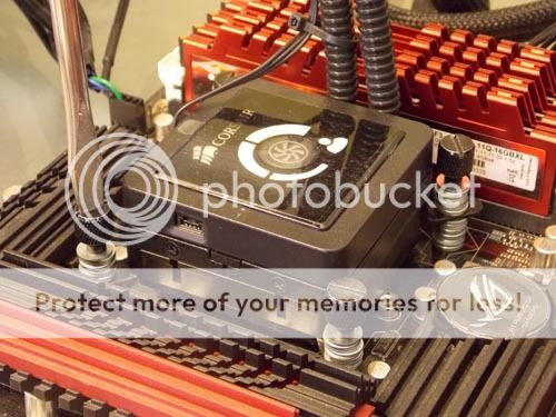
^ look at the sliver of black colored metal in the upper-right corner of this pic, it is slipped in the stack of washers. Each washer is 1mm, the black metal that forms the H100 mount bracket is thinner than one washer and flexes when mounted.
Here's a more clear image of the bracket in question, different washers here though so don't get the dimensions confused:
I wonder though, is there a noticeable difference between having the IHS and not (after deliding/polishing)?
Not sure which paste you used in the original deliding, but perhaps you could list those results next to the same paste results with the IHS off.
Yeah the difference wasn't so much, 4°C tops, those results were all done with NT-H1 TIM and are posted in this post: Results of Direct-Die Mount with H100 (no IHS)
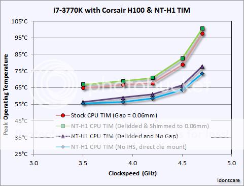
^ for the purposes of your question you are interested in the results between the purple line (with triangles) versus the blue line (with diamonds). That is your "w/IHS vs. w/o IHS" test using the exact same TIM on the CPU (NT-H1).
Arctic Silver 5, aka AS5, is perhaps the most well known TIM in the enthusiast community. It feels like it has been around for decades.
AS5 holds a special place for me because it was the first 3rd party TIM I used that wasn't the stock TIM recommended by the CPU or HSF manufacturer. And while it has gotten long in the tooth over the past 10yrs or so, it still performs surprisingly well relative to its more modernized and sophisticated rivals.
As was true of Céramique, made by the same company, I could not locate any technical specs for AS5 from the manufacturer in terms of thermal performance or viscosity.
And just like Céramique, AS5 requires an extensive break-in period per the manufacturer if you want to extract maximum thermal conductivity from the TIM:
So what do we see from AS5 in the un-maximized condition of being freshly applied and mounted?

^ does that AS5 look funky to you? It looks funky (runny?) to me, but according to Arctic Silver it is just fine:
After the tests:


^ you see in this image on the H100 what I was referring to above when I posted that it was difficult to cleanly separate the CPU from the waterblock with some of these TIMs because the CPU stuck to the H100 so well. This was one of those cases, I was able to lift the CPU off the H100 but then it tipped and fell back onto it, muddling the mounting imprint.

The results with AS5 were nothing to write home about, not bad (not IC Perihelion bad 😛) but they also weren't anything to make me have second thoughts about removing it and testing the next TIM without looking back.
As we saw previously, Céramique performed slightly better than AS5. Alas, regardless how great AS5 may perform after 200hrs of break-in time this TIM reportedly suffers from the so-called "pump out effect" when applied directly to the exposed die like this. So the result is an interesting box to check but really represents nothing more at this stage.
AS5 holds a special place for me because it was the first 3rd party TIM I used that wasn't the stock TIM recommended by the CPU or HSF manufacturer. And while it has gotten long in the tooth over the past 10yrs or so, it still performs surprisingly well relative to its more modernized and sophisticated rivals.
As was true of Céramique, made by the same company, I could not locate any technical specs for AS5 from the manufacturer in terms of thermal performance or viscosity.
And just like Céramique, AS5 requires an extensive break-in period per the manufacturer if you want to extract maximum thermal conductivity from the TIM:
Uh, 200hrs!? D: Sorry, I'll test this TIM out at stock, time-zero, conditions but I'm not that interested in seeing if it will marginally improve over the course of a week or two :whiste: Not when I can have even better results from other available TIMs without having to wait 7-10 days.Important Reminder:
Due to the unique shape and sizes of the particles in Arctic Silver 5's conductive matrix, it will take a up to 200 hours and several thermal cycles to achieve maximum particle to particle thermal conduction and for the heatsink to CPU interface to reach maximum conductivity. (This period will be longer in a system without a fan on the heatsink or with a low speed fan on the heatsink.) On systems measuring actual internal core temperatures via the CPU's internal diode, the measured temperature will often drop 2C to 5C over this "break-in" period. This break-in will occur during the normal use of the computer as long as the computer is turned off from time to time and the interface is allowed to cool to room temperature. Once the break-in is complete, the computer can be left on if desired.
So what do we see from AS5 in the un-maximized condition of being freshly applied and mounted?
^ does that AS5 look funky to you? It looks funky (runny?) to me, but according to Arctic Silver it is just fine:
Absolute Stability:
Arctic Silver 5 will not separate, run, migrate, or bleed.
After the tests:
^ you see in this image on the H100 what I was referring to above when I posted that it was difficult to cleanly separate the CPU from the waterblock with some of these TIMs because the CPU stuck to the H100 so well. This was one of those cases, I was able to lift the CPU off the H100 but then it tipped and fell back onto it, muddling the mounting imprint.
The results with AS5 were nothing to write home about, not bad (not IC Perihelion bad 😛) but they also weren't anything to make me have second thoughts about removing it and testing the next TIM without looking back.
As we saw previously, Céramique performed slightly better than AS5. Alas, regardless how great AS5 may perform after 200hrs of break-in time this TIM reportedly suffers from the so-called "pump out effect" when applied directly to the exposed die like this. So the result is an interesting box to check but really represents nothing more at this stage.
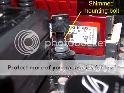
Question: When does putting ~50 washers on your motherboard turn into a bad idea?

Answer: When you herp-a-derp and forget they are there as you turn your mobo over to confirm the H100 mounting bracket is still just fine from the backside :|

I had heard of the game "52 card pickup", and now I've played the game "50 washer pickup". Will not be making that same mistake twice 😡
OK, back on-topic, Tuniq TX-1, a TIM so old that not even Tuniq will acknowledge its existence with a link to its servers 😛
I have no idea how or why I came to accumulate so much of it, must have been a freebie thrown in with a bunch of Tuniq Towers I bought a while ago?
The side of the tube states the thermal conductivity is 3.3W/m-K which I am willing to believe because that would put it at the bottom of my TIMs in terms of thermal conductivity and this TIM certainly came in at the bottom of the list in terms of resulting CPU temperature (it was the worst of them all).
Applying the TIM went fine, its like MX-4 in every way except for its thermal performance. Cleaned up super easy too.

Gave a nice mount, made for some pretty macro-pics:


However, performance-wise all I can conclude is that there is VERY good reason why Tuniq is now on version 4 (TX-4) having left this first version (TX-1) in the dust:

This was the worst performing of the bunch, even managed to be worse than IC Perihelion. Temps were so hot at 4.7GHz that I didn't attempt to run the 4.8 or 4.9GHz tests.
Answer: When you herp-a-derp and forget they are there as you turn your mobo over to confirm the H100 mounting bracket is still just fine from the backside :|
I had heard of the game "52 card pickup", and now I've played the game "50 washer pickup". Will not be making that same mistake twice 😡
OK, back on-topic, Tuniq TX-1, a TIM so old that not even Tuniq will acknowledge its existence with a link to its servers 😛
I have no idea how or why I came to accumulate so much of it, must have been a freebie thrown in with a bunch of Tuniq Towers I bought a while ago?
The side of the tube states the thermal conductivity is 3.3W/m-K which I am willing to believe because that would put it at the bottom of my TIMs in terms of thermal conductivity and this TIM certainly came in at the bottom of the list in terms of resulting CPU temperature (it was the worst of them all).
Applying the TIM went fine, its like MX-4 in every way except for its thermal performance. Cleaned up super easy too.
Gave a nice mount, made for some pretty macro-pics:
However, performance-wise all I can conclude is that there is VERY good reason why Tuniq is now on version 4 (TX-4) having left this first version (TX-1) in the dust:
This was the worst performing of the bunch, even managed to be worse than IC Perihelion. Temps were so hot at 4.7GHz that I didn't attempt to run the 4.8 or 4.9GHz tests.
Turning now to TX-1's successor, i.e. Tuniq TX-2, the results are much improved and prove that TX-2 was a worthy replacement of TX-1...so much so that Tuniq will at least admit it created the product by linking to it on their website 😀
According to the manufacturer, the technical specs for this TIM are 4.5 W/m-K (thermal conductivity), 2850 poise (viscosity), and 3.96 g/cm³ (density).
TX-2 is very easy to apply, and very easy to cleanup and remove with some IPA and a paper towel.

It gives a good mount, wasn't difficult to get the right amount of TIM onto the die:


And the performance was quite comparable to that of AS5 (just a smidgen worse than AS5), enabling the full range of OC'ing speeds:

Surprisingly TX-2 performed better than MX-4, and the MX-4 results are not a fluke (I mounted the MX-4 three separate times to confirm the results).
According to the manufacturer, the technical specs for this TIM are 4.5 W/m-K (thermal conductivity), 2850 poise (viscosity), and 3.96 g/cm³ (density).
TX-2 is very easy to apply, and very easy to cleanup and remove with some IPA and a paper towel.
It gives a good mount, wasn't difficult to get the right amount of TIM onto the die:
And the performance was quite comparable to that of AS5 (just a smidgen worse than AS5), enabling the full range of OC'ing speeds:
Surprisingly TX-2 performed better than MX-4, and the MX-4 results are not a fluke (I mounted the MX-4 three separate times to confirm the results).
thilanliyan
Lifer
Really never expected ceramique to do so well! I'm using mx4 myself for both cpu and gpu...maybe I should consider something else next time I take my loop apart.
TacoRanger
Junior Member
Can't wait for the IC Diamond test as well. I use IC Diamond 7 and it's a pretty good TIM in my opinion. My FX-4100 get's to ~64C at 4.4GHz. I haven't tested it in a while and don't remember the exact temperatures.
Really never expected ceramique to do so well! I'm using mx4 myself for both cpu and gpu...maybe I should consider something else next time I take my loop apart.
I'm kinda shocked it spread out so good....That stuff if pretty thick and kinda hard to work with from what I remember. Last time I used it was on my GPU water block a couple years ago....Seems to be holding up just fine to this day.
exar333
Diamond Member
2 comments:
-Thanks to IDC for such a great, detailed, and useful review of the TIMs that most people use as a matter of course. I am also curious about IC Diamond, as I have found this TIM VERY good, replacing my Noctua paste.
-The '50-washer pickup' post made me laugh out loud, seriously. That's something I would do..🙂
OK, now we are finally getting to the good stuff :awe: IC Diamond is considered to be a premier TIM, and not just because "it has diamonds in it!" but because it tends to produce superior cooling results compared to the more traditional metal-oxide based TIMs (AS5, NT-H1, etc).
Interestingly though, according to the manufacturer this TIM has the same thermal conductivity as TX-2, coming in right at 4.5 W/m-K.
In terms of ease-of-use the IC Diamond TIM is not all that stellar. It is thick and pasty, albeit not as bad as IC Perihelion (/shudders D🙂, but it is certainly more difficult to spread than say NT-H1 or MX-4.
Likewise with the cleaning factor if and when you should decide you want to remove it. It is not as simple as wiping down the surfaces with paper towel containing IPA, although you can leave the cleanup detail to be something as simple as that. In my case it irreversibly marred the surface of the bare silicon die (looks like it abraded it, like I hit the die with a touch of 400 grit sand paper).
However, for all I can tell these surface alterations are entirely superficial and do not actually degrade or impede the thermal performance of the surfaces with other TIMs even after the fact. So I mention it here simply for the sake of completeness. Do not use IC Diamond on your bare silicon die unless you are prepared to be OK with what appear to be surface scratches on the die as well as the possibility of your HSF looking like the following:

^ that is after rigorous cleaning with IPA. The stains are easily removed by relapping the HSF with 800 grit, followed by 2000 and 3000 grit to get back to mirror polish.
OK, so enough about the cleanup issues related to using IC Diamond, lets look at some pretty pics!
Before the mount:

^ this quantity of ICD turned out to be the "optimal" amount as you will see later on 😉
Pulling the mount after the tests shows us how the die looked:

And the H100 block:

And the temperature data:

Interestingly enough these results are neck-and-neck tied with the results obtained using Céramique.
One bit of difference between the two of course is that IC Diamond is designed to avoid suffering from the pump-out effect, so these results should hold up for the long-term duration whereas the Céramique results would be expected to degrade in time as the Céramique itself ends up getting pumped out from between the cpu die and the H100 surfaces.
OK, but what about testing with even less IC Diamond to see if maybe we got too much onto the die in the first place?
I reran the tests above only this time I used half (50%) of the ICD as I used in the first test. I don't have a picture of the pre-mount or the post-mount for the cpu die itself (no idea why, I thought I took pics of everything but those shots didn't show up in my library) but I do have a picture of the H100 after the unmount which clearly shows the entire die imprint indicating the die was fully covered (which is also what I remember seeing with my own eye).

^ H100 imprint of die coverage with IC Diamond for the test dubbed "50% ICD" in the table below.

These data show that going with too little IC Diamond, even though you still get full die coverage on the exposed silicon die, can result in markedly poorer thermal performance in the neighborhood of ~7°C higher temperatures for the higher clockspeeds versus the results that can be achieved by using an optimal amount of ICD.
I don't know if this experience holds true for the more traditional applications of IC Diamond in which it is being used as a TIM between the IHS and the HSF, but for you ICD users out there it might be worth exploring and taking a look to see if you use a little more ICD than you otherwise might need to get 100% surface coverage if your thermals improve as mine did here.
Interestingly though, according to the manufacturer this TIM has the same thermal conductivity as TX-2, coming in right at 4.5 W/m-K.
In terms of ease-of-use the IC Diamond TIM is not all that stellar. It is thick and pasty, albeit not as bad as IC Perihelion (/shudders D🙂, but it is certainly more difficult to spread than say NT-H1 or MX-4.
Likewise with the cleaning factor if and when you should decide you want to remove it. It is not as simple as wiping down the surfaces with paper towel containing IPA, although you can leave the cleanup detail to be something as simple as that. In my case it irreversibly marred the surface of the bare silicon die (looks like it abraded it, like I hit the die with a touch of 400 grit sand paper).
However, for all I can tell these surface alterations are entirely superficial and do not actually degrade or impede the thermal performance of the surfaces with other TIMs even after the fact. So I mention it here simply for the sake of completeness. Do not use IC Diamond on your bare silicon die unless you are prepared to be OK with what appear to be surface scratches on the die as well as the possibility of your HSF looking like the following:
^ that is after rigorous cleaning with IPA. The stains are easily removed by relapping the HSF with 800 grit, followed by 2000 and 3000 grit to get back to mirror polish.
OK, so enough about the cleanup issues related to using IC Diamond, lets look at some pretty pics!
Before the mount:
^ this quantity of ICD turned out to be the "optimal" amount as you will see later on 😉
Pulling the mount after the tests shows us how the die looked:
And the H100 block:
And the temperature data:
Interestingly enough these results are neck-and-neck tied with the results obtained using Céramique.
One bit of difference between the two of course is that IC Diamond is designed to avoid suffering from the pump-out effect, so these results should hold up for the long-term duration whereas the Céramique results would be expected to degrade in time as the Céramique itself ends up getting pumped out from between the cpu die and the H100 surfaces.
Bake out and pump out are well known and documented as primary causes of grease failure. A viable or optimal compound is one that utilizes as little of any kind material (liquids)as possible that would be the central cause of of a TIM joint failure, while at the same time maintaining the best thermal performance possible. With the introduction of IC Diamond Thermal Compound we believe we have managed all the criteria for an optimal TIM by combining both performance and reliability.
http://www.innovationcooling.com/Reliabilty1.htm
OK, but what about testing with even less IC Diamond to see if maybe we got too much onto the die in the first place?
I reran the tests above only this time I used half (50%) of the ICD as I used in the first test. I don't have a picture of the pre-mount or the post-mount for the cpu die itself (no idea why, I thought I took pics of everything but those shots didn't show up in my library) but I do have a picture of the H100 after the unmount which clearly shows the entire die imprint indicating the die was fully covered (which is also what I remember seeing with my own eye).
^ H100 imprint of die coverage with IC Diamond for the test dubbed "50% ICD" in the table below.
These data show that going with too little IC Diamond, even though you still get full die coverage on the exposed silicon die, can result in markedly poorer thermal performance in the neighborhood of ~7°C higher temperatures for the higher clockspeeds versus the results that can be achieved by using an optimal amount of ICD.
I don't know if this experience holds true for the more traditional applications of IC Diamond in which it is being used as a TIM between the IHS and the HSF, but for you ICD users out there it might be worth exploring and taking a look to see if you use a little more ICD than you otherwise might need to get 100% surface coverage if your thermals improve as mine did here.
TRENDING THREADS
-
 Discussion Zen 5 Speculation (EPYC Turin and Strix Point/Granite Ridge - Ryzen 9000)
- Started by DisEnchantment
- Replies: 25K
-
Discussion Intel Meteor, Arrow, Lunar & Panther Lakes + WCL Discussion Threads
- Started by Tigerick
- Replies: 25K
-
 Discussion Intel current and future Lakes & Rapids thread
- Started by TheF34RChannel
- Replies: 24K
-

-
