Discussion Intel Meteor, Arrow, Lunar & Panther Lakes + WCL Discussion Threads

Page 675 - Seeking answers? Join the AnandTech community: where nearly half-a-million members share solutions and discuss the latest tech.

Tigerick

Senior member
Apr 1, 2022
921
836
106
Wildcat Lake (WCL) Preliminary Specs

Intel Wildcat Lake (WCL) is upcoming mobile SoC replacing ADL-N. WCL consists of 2 tiles: compute tile and PCD tile. It is true single die consists of CPU, GPU and NPU that is fabbed by 18-A process. Last time I checked, PCD tile is fabbed by TSMC N6 process. They are connected through UCIe, not D2D; a first from Intel. Expecting launching in Q2/Computex 2026. In case people don't remember AlderLake-N, I have created a table below to compare the detail specs of ADL-N and WCL. Just for fun, I am throwing LNL and upcoming Mediatek D9500 SoC.

Intel Alder Lake - NIntel Wildcat LakeIntel Lunar LakeMediatek D9500
Launch DateQ1-2023Q2-2026 ?Q3-2024Q3-2025
ModelIntel N300?Core Ultra 7 268VDimensity 9500 5G
Dies2221
NodeIntel 7 + ?Intel 18-A + TSMC N6TSMC N3B + N6TSMC N3P
CPU8 E-cores2 P-core + 4 LP E-cores4 P-core + 4 LP E-coresC1 1+3+4
Threads8688
Max Clock3.8 GHz?5 GHz
L3 Cache6 MB?12 MB
TDP7 WFanless ?17 WFanless
Memory64-bit LPDDR5-480064-bit LPDDR5-6800 ?128-bit LPDDR5X-853364-bit LPDDR5X-10667
Size16 GB?32 GB24 GB ?
Bandwidth~ 55 GB/s136 GB/s85.6 GB/s
GPUUHD GraphicsArc 140VG1 Ultra
EU / Xe32 EU2 Xe8 Xe12
Max Clock1.25 GHz2 GHz
NPUNA18 TOPS48 TOPS100 TOPS ?


PPT1.jpg
PPT2.jpg
PPT3.jpg


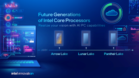
As Hot Chips 34 starting this week, Intel will unveil technical information of upcoming Meteor Lake (MTL) and Arrow Lake (ARL), new generation platform after Raptor Lake. Both MTL and ARL represent new direction which Intel will move to multiple chiplets and combine as one SoC platform.

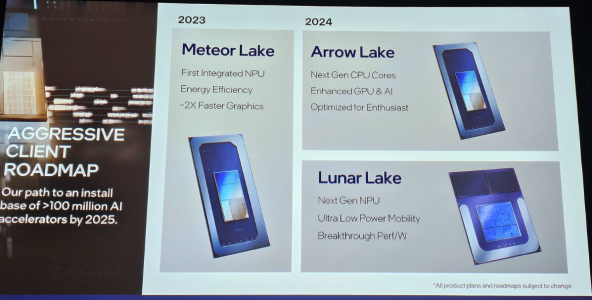
MTL also represents new compute tile that based on Intel 4 process which is based on EUV lithography, a first from Intel. Intel expects to ship MTL mobile SoC in 2023.

ARL will come after MTL so Intel should be shipping it in 2024, that is what Intel roadmap is telling us. ARL compute tile will be manufactured by Intel 20A process, a first from Intel to use GAA transistors called RibbonFET.


LNL-MX.png
 

Attachments

  • PantherLake.png
    PantherLake.png
    283.5 KB · Views: 24,034
  • LNL.png
    LNL.png
    881.8 KB · Views: 25,527
  • INTEL-CORE-100-ULTRA-METEOR-LAKE-OFFCIAL-SLIDE-2.jpg
    INTEL-CORE-100-ULTRA-METEOR-LAKE-OFFCIAL-SLIDE-2.jpg
    181.4 KB · Views: 72,435
  • Clockspeed.png
    Clockspeed.png
    611.8 KB · Views: 72,321
Last edited:

Krteq

Golden Member
May 22, 2015
1,010
730
136
Lol, x86-64-v3 is using only AVX2, not AVX512.

AVX512 is used in x86-64-v4 and there is also znver5 option with more AVX512 instructions implemented
 
  • Like
Reactions: Tlh97

Hitman928

Diamond Member
Apr 15, 2012
6,748
12,474
136
It's structure silicon on top of CPU tiles. MI300 has two compute tiles per base tile yet its not visible in pictures either, it just looks like a singular tile

Why would you need structural silicon on the top?

For MI300, you can't see the distinction between the dies from low res/zoomed in photos and bad lighting/angle, but you can see the division with a high enough resolution photo and good lighting/angle. My guess would be the same is true with CWF.

Example MI300 -

Bad photo:

1731430081172.png

Good photo:

1731430187602.jpeg
 
  • Like
Reactions: Tlh97

cannedlake240

Senior member
Jul 4, 2024
247
138
76
Why would you need structural silicon on the top?

For MI300, you can't see the distinction between the dies from low res/zoomed in photos and bad lighting/angle, but you can see the division with a high enough resolution photo and good lighting/angle. My guess would be the same is true with CWF.

Example MI300 -

Bad photo:

View attachment 111500

Good photo:

View attachment 111501
Doesn't it have 2 compute tiles per 1 base tile?
 

Hitman928

Diamond Member
Apr 15, 2012
6,748
12,474
136
Doesn't it have 2 compute tiles per 1 base tile?

The base tile spans everything, all the compute, HBM, etc. The compute dies are part of an active interposer and there are 4 active interposer dies per MI300. I thought this was what you were referring to, but if you mean the compute tiles per active interposer, then yes, there are 2. Those are surrounded by structural silicon, AFAIK, and very difficult to make out as the process makes them seem continuous from the naked eye (unless you start delayering the chips), similar to the Zen 3/4 dies V-cache chips. CWF could have structural silicon around the compute dies causing the same visual issue. I wouldn't think they would need it, but it's certainly possible.
 
Last edited:
  • Like
Reactions: Tlh97 and DavidC1

Hitman928

Diamond Member
Apr 15, 2012
6,748
12,474
136
Just need someone to destroy Clearwater forest CPU to see what's it like

I think the Intel slide makes it pretty clear. The smaller details like support silicon are interesting (to me at least), but not important to the performance/functionality of the chips.
 

MS_AT

Senior member
Jul 15, 2024
913
1,830
96
For those results here are the flags and the reason for using gcc 10
I fail to see from this message why gcc 10 was used. It is also no suprise that march=native mtune=native would give him bad results as these CPUs are younger by couple of years than this compiler version. Its from 2020, the newest Zen it recognizes is Zen3. Since it does not recognize the target it will default to generic.

x86-64-v3 is probably the newest that version of compiler recognizes, v4 was introduced later if I am not mistaken and this, as was already mentioned in the thread, tops at avx2.
 
  • Like
Reactions: Tlh97 and Elfear

Saylick

Diamond Member
Sep 10, 2012
4,099
9,578
136
What do you mean weird magical warpage?
Materials will expand and contract under thermal loading. Silicon is no exception. Warping can occur when you have one portion of the package heating up more than another side. On a monolithic die, it's not a big problem because it's all part of the same die. When you have chiplets/tiles, there's no continuity between them so heat doesn't distribute as evenly, causing warping. Having a slab of structural silicon tying things together helps to minimize potential warping.
 
  • Like
Reactions: 511

Hitman928

Diamond Member
Apr 15, 2012
6,748
12,474
136
Materials will expand and contract under thermal loading. Silicon is no exception. Warping can occur when you have one portion of the package heating up more than another side. On a monolithic die, it's not a big problem because it's all part of the same die. When you have chiplets/tiles, there's no continuity between them so heat doesn't distribute as evenly, causing warping. Having a slab of structural silicon tying things together helps to minimize potential warping.

Sure, but there are other ways around this. Many 3d stacked chips don't keep the carrier wafer. . .

I also wouldn't call this "magical warpage" as it's something that's very well known.

Edit: Just to be clear, I'm not saying keeping the carrier wafer isn't in big part for thermal warping concerns, just that if that is what was meant, just say it rather than insinuate some weird unknown source of warping that only the carrier silicon can solve.
 
Last edited:

maddie

Diamond Member
Jul 18, 2010
5,183
5,580
136
Materials will expand and contract under thermal loading. Silicon is no exception. Warping can occur when you have one portion of the package heating up more than another side. On a monolithic die, it's not a big problem because it's all part of the same die. When you have chiplets/tiles, there's no continuity between them so heat doesn't distribute as evenly, causing warping. Having a slab of structural silicon tying things together helps to minimize potential warping.
Also the different materials with their unique expansion coefficients cause extreme strains across the die. Fatigue failures due to thermal expansion stress is a thing.
 

511

Diamond Member
Jul 12, 2024
5,123
4,606
106
I fail to see from this message why gcc 10 was used. It is also no suprise that march=native mtune=native would give him bad results as these CPUs are younger by couple of years than this compiler version. Its from 2020, the newest Zen it recognizes is Zen3. Since it does not recognize the target it will default to generic.

x86-64-v3 is probably the newest that version of compiler recognizes, v4 was introduced later if I am not mistaken and this, as was already mentioned in the thread, tops at avx2.
Yes but what is the issue if at max if it supports AVX2 they all support it except Zen5 which supports 512 as well a clear baseline and regarding compilers we talk as people use Zenver4/5 flags even Huang uses zenver3 sure the compiler version and settings may leave things to be desired but Intel is at the same settings 🙂
 

Hitman928

Diamond Member
Apr 15, 2012
6,748
12,474
136
PHYs on the AIDs can get real toasty and cause warpage abound. It's why -R slab was ditched in favour of conventional -S.

The carrier wafer doesn't touch the AIDs though. I'm not a mechanical engineer, but I don't see how it helps if the middle die that the carrier wafer isn't attached to is the issue. It would make more sense to me that you want the carrier wafer there to avoid warping from thermal expansion when the compute dies are hot.

I can see switching from COWOS-R to COWOS-S for thermal expansion concerns as it is one big slab that all of the AIDs connect to, so AID heat causing warping at the base level makes a lot of sense.
 

MS_AT

Senior member
Jul 15, 2024
913
1,830
96
Yes but what is the issue if at max if it supports AVX2 they all support it except Zen5 which supports 512 as well a clear baseline and regarding compilers we talk as people use Zenver4/5 flags even Huang uses zenver3 sure the compiler version and settings may leave things to be desired but Intel is at the same settings 🙂
There is no issue. It's just somebody asked why Zen5 is doing well in FP, quoting these spec results, you answered thanks to AVX512, thing is it couldn't be thanks to that because it was not enabled;)

Another thing is, if the first round of tests he did was gcc 10 march=native, mtune=native then it will inflate Skymont scores compared to LionCove, that is something to keep in mind.

All I am saying is that compiler options matter, and it is good to be aware of they do and interpret the SPEC results with this in mind;)
 

DavidC1

Platinum Member
Dec 29, 2023
2,021
3,157
96
The thing is the 18A dies are under the Intel 3 dies and they are distant apart from the initial diagram each die has distance between them which will slice the area same issue as Zen5X3D
This makes no sense. It would need to go through a layer to the heatsink and make it more difficult to cool. The base layer is SRAM and IO which uses much less power. The top has to be 18A compute.

The picture you linked clearly shows the base tile is at the BOTTOM, with 12 dies at the top.

Something little different: Apple M4 generation is getting 2000 points at just 60W of power. It absolutely can and will demolish in server if they decided to make a chip based on it. Apple is too consumer focused, but there's a potential.

When talking about theoreticals, inserting artificially imposed restrictions(such as the ISA/compatibility barrier) makes no sense. A CPU with a superior uarch resulting in much better performance and performance per watt will be better in everything.

M4 is a clear indication that even Intel E cores can do much, much better. 30% per clock in Arctic Wolf, and 40-50% on top of that by aiming for 2.xmm2 core in the UC generation will do a "Conroe moment" again. Not something incredible for a 2028 core. Good, but not incredible.
 
Last edited:
  • Like
Reactions: Tlh97

511

Diamond Member
Jul 12, 2024
5,123
4,606
106
The picture i showed were 1 presentation from Intel docs the second is the real image of CLWF from Serve the home
 

DavidC1

Platinum Member
Dec 29, 2023
2,021
3,157
96
The picture i showed were 1 presentation from Intel docs the second is the real image of CLWF from Serve the home
Yes and real pics of the 2.5D products are usually much closer between the dies. Look at Ponte Vecchio's artistic rendition over actual shots. Again it makes no sense to have 18A under the IO die. There has to be a specific reason if they did as you suggested because of things like thermal issues.

You aren't seeing the divisions because of camera angle for one.