Delidded my i7-3770K, loaded temperatures drop by 20°C at 4.7GHz

Page 4 - Seeking answers? Join the AnandTech community: where nearly half-a-million members share solutions and discuss the latest tech.

cbn

Lifer
Mar 27, 2009
12,968
221
106
Imagine how well it would do with solder?

Well, at least we know Intel's 22nm process isn't that hampered by heat density yet.

(Based on what I have read solder is much much better at conducting heat than even the very best aftermarket TIM.)

Still, I agree, it would be nice to see what 22nm could do with the same material used under a Sandy Heat spreader.
 

Idontcare

Elite Member
Oct 10, 1999
21,118
58
91
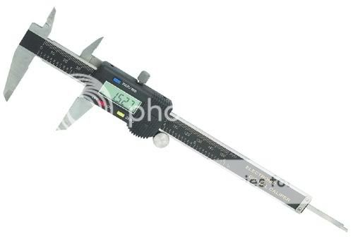
To answer one of the questions that is on many of our minds - "what is the gap between the CPU and the underside of the IHS?" - I took a bevy of measurements using a digital caliper that purports to have an accuracy of ±0.03mm (that's 30μm).

Micrometer.jpg


True to the enthusiast spirit of doing things as cheaply as possible, this is a silly cheap caliper from Harbor Freight weighing in at an amazingly inexpensive $20 :eek: (I paid only $10 for it a few months ago it as a door-buster promo item). And despite its price, I was surprised it actually works as well as advertised, cheap as chips as it were.

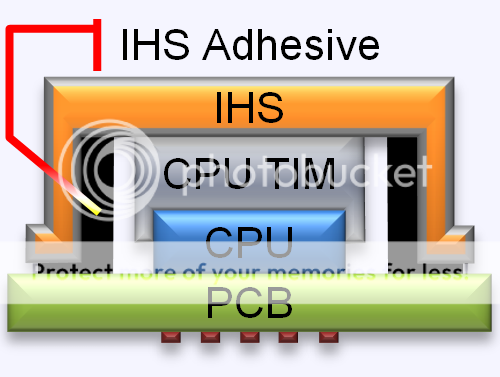
First, before we get into the measurements themselves, I felt we needed to establish some common-ground in terms of nomenclature so I don't confuse everyone (myself included). To that end, I created a goofy little drawing in powerpoint which I then overlaid in the pics to highlight what it is that I was measuring in that picture.

Here is our schematic for the cross-section of the IB CPU package - note absolutely nothing is to scale, the sizes are NOT relative. I just sized everything so the labels were legible, for example the CPU TIM isn't really that thick compared to the CPU, etc.

SchematicofCPUpackagecross-section.png

So you can see what I refer to as the "PCB", it is the green part of the CPU package that the CPU is connected to from above, and the LGA pads are underneath, with the capacitors (not labeled) located directly under the footprint of the CPU silicon die.

Also we see what I refer to as the "CPU TIM" being the thermal interface material located between the CPU silicon die and the underside of the IHS.

Likewise I refer to the black rubbery adhesive layer that binds the IHS to the PCB as "IHS adhesive".

Now for the measurements, this is the full stack thickness as measured prior to the delidding but after I had lapped the IHS, I measure 4.21 mm:

i7-3770Kfullthickness-1.jpg


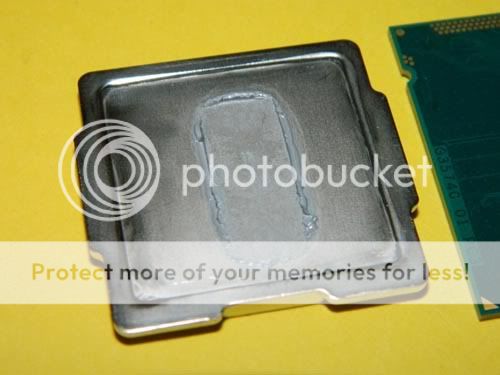
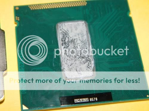
Then I removed all the IHS adhesive (detailed in this post) and all the CPU TIM from the CPU and the underside of the IHS, and restacked the IHS onto the PCB over the top of the CPU without any CPU TIM.

One of the questions we want to answer is "with the IHS adhesive removed, is there a gap between the CPU and the underside of the IHS for more CPU TIM to occupy or is the gap between the IHS and the PCB because the IHS itself is resting on top of the CPU?"

Whichgapisit.png


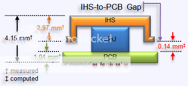
The resulting stack measured 4.15 mm, 0.06 mm thinner than the initial thickness:

PCBCPUIHSmeasurement.jpg


From these measurements we see that the IHS adhesive that binds the IHS to the PCB must have lifted the IHS off of the PCB by at least 0.06 mm. (at this point we still don't know if the IHS is resting on the PCB or on the CPU die)

To answer this question we need to determine how shallow or deep the IHS recess is within which the CPU and CPU TIM reside. To make that measurement we must take two measurements and subtract them to arrive at the result.

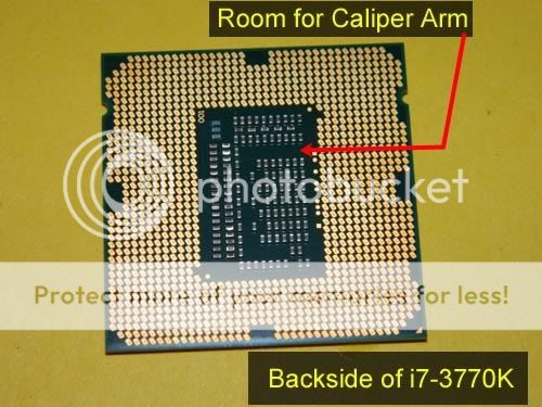
First, lets determine how thick (tall) the CPU die silicon is. To make this measurement I took advantage of the layout of the capacitors on the underside of the PCB, there is one little zone which I could snake the caliper tip into so the I got a good measurement of the CPU + PCB.

Backsideofi7-3770k.jpg


The CPU and the PCB weigh in at 1.57 mm, the result was repeatable, I remeasured it three times and it measured 1.57 mm each time.

CPUPCBmeasurement1noadhesive.jpg


^ notice how silly thin the CPU actually is, it barely sticks up above the PCB, by eye it looks like just a tiny little bump, perhaps half a millimeter.

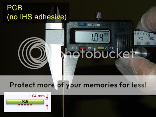
Next, measuring just the PCB's thickness, I get 1.04 mm:

PCBmeasurement1noadhesive.jpg


This leaves us to conclude the CPU silicon die is a mere 0.53 mm thick (1.57 - 1.04). That is very thin.

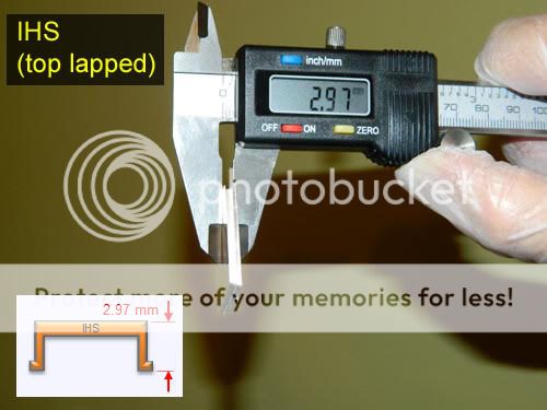
Next I measured the thickness of the IHS (this is after I lapped it, mind you), 2.97 mm:

IHSnoadhesive.jpg


(due to a 10 image limit per post, the remainder of this post will be continued in the next post)
 

Idontcare

Elite Member
Oct 10, 1999
21,118
58
91
(...continued from the OP above)

Putting these data together, we can compute whether or not a gap exists between the CPU and the underside of the IHS or if the gap exists between the IHS and the PCB:

IHStoPCBGap.png


The math tells us the IHS is sitting on top of the CPU, held aloft and creating a gap some 0.14mm to the PCB.

Now I can verify by eye that a gap between the IHS and the PCB does indeed exist, but it is an extremely small gap (as the number would indicate) and attempts to take a photo detailing the gap is pretty challenging. I took a lot of different pics, varied the lighting, etc, and here is the best I could come up with:

SideshotofIHStoPCBgap.jpg


But perhaps the most compelling argument that I can make to support the assertion that the IHS is resting on top of the CPU once you delid the IHS and remove the black rubbery adhesive and CPU TIM is the following video I took in which I could freely rotate (spin) the IHS while it sits on top of the CPU and PCB...it wouldn't spin so freely if it were resting or contacting the PCB at any point.

SpinningIHSshortfinal.gif


^ you can see a much higher quality version of this video, also longer and showing more spins, in this youtube video.

So in the OP where I showed results from using NT-H1 as the replacement CPU TIM under the IHS, the TIM was the only thing keeping the IHS from being pressed down onto the bare die.

When I took the IHS off, after the testing was complete, sure enough there was very little TIM remaining on the IHS in the region where the CPU makes contact. A lot of the NT-H1 had been squeezed out to the side.

IHSdeliddedpostNT-H1test1.jpg


But not all of it was squeezed out, look at how much TIM is still clearly covering the CPU die in the following photo:

i7-3770kdeliddedpostNT-H1test1.jpg


Some of you might be wondering why the two lower corners of the silicon die in the above photo look black, like they've been chipped off...which is certainly a concern now that we know the IHS is sitting on the die here.

Well I'm happy to report I confirmed the corners are fully intact, no chipping whatsoever. What looks like chipped corners above is actually just the corners of the die that are not covered by TIM, the contact was great enough that the TIM never touched that part of the die during the mount.

Now that we know the gap between the IHS and the CPU is basically whatever thickness the CPU TIM ends up being under pressure of the mount, this will be quite intriguing to test the thermal efficacy of the various TIMs as well as lapping/polishing the underside of the IHS itself. ;)
 

HondaCop

Member
Aug 4, 2012
42
0
0
IDC, you sir, are a class act. This is by far one of the best and most interesting threads I've ever read with regards to our overclocking vice.

Just so you know, I am also running a butt naked 3770K. It's been de-lidded and glue cleaned away. I don't know if you noticed, but if you place the IHS on the cpu, you can feel it rock from side to side if you put light down pressure on the edges of the IHS. The IHS is most definitely resting on the die. If we lap the underside of the IHS, wouldn't that create a gap between the IHS and die? Wouldn't that be a bad thing? If not, how would we even lap that area being it's so hard to reach.

Is this a good thing? BTW, I will be using Liquid Metal Ultra very soon on my cpu! Either today or tomorrow, if it arrives on time.


- Grammar *censored*, this was sent from my phone.
 
Last edited:

Haserath

Senior member
Sep 12, 2010
793
1
81
Very nice threads IDC.:thumbsup: I may not have Ivy, but I love the info. You're bookmarked.

You have inspired me to lap my 920 and CM 212. Hoping to move the push-pull config down to one fan while staying under 70C. Thinking about repasting my Vcard, and will definitely get some data if I get the kahooches to do so.
 

ShintaiDK

Lifer
Apr 22, 2012
20,378
145
106
Spinning the IHS on the die. LOL, time for the ward for you!

But very nice reading. :thumbsup:
 

dma0991

Platinum Member
Mar 17, 2011
2,723
1
0
Got to get myself one of those calipers. All I had was a plastic version without digital readout, got burnt and good riddance. Great write up BTW!:thumbsup:
 

Kenmitch

Diamond Member
Oct 10, 1999
8,505
2,249
136
So far it's looking like too much not so good TIM is the issue out of the box. The original TIM looks very strange. Reminds me of the stock TIM from the Intel heatsinks....At least from the images anyways.

Interesting thread :)
 

HondaCop

Member
Aug 4, 2012
42
0
0
Man, I'm so desperate to get my Liquid Metal Ultra! Speaking of which, is LMU safe to be used on the cpu die? Or should I only use it on the IHS to H100 side of things?
 

Diogenes2

Platinum Member
Jul 26, 2001
2,151
0
0
Food for thought..
I am contemplating doing this ( ...with an IB I have - not my sig rig. ), and want to try Tuniq Tx-4 ..
I wasn't able to get any locally, so was thinking about using some IC Diamond 7 Carat that I have, and know works very well, but then remembered that the IC Diamond will etch the top of the IHS.
I don't think etching the top of the CPU silicon would be a good idea, so I'm glad I thought this through before going ahead..
 

Yuriman

Diamond Member
Jun 25, 2004
5,530
141
106
Thanks much! I wonder if we could get someone to manufacture a shim to go between the PCB and IHS and make the gap smaller? I'm concerned that my method of mounting my waterblock (bolts/nuts) might not be safe.

Perhaps getting longer bolts and adding springs will help in my case.
 

Kenmitch

Diamond Member
Oct 10, 1999
8,505
2,249
136
Thanks much! I wonder if we could get someone to manufacture a shim to go between the PCB and IHS and make the gap smaller? I'm concerned that my method of mounting my waterblock (bolts/nuts) might not be safe.

Perhaps getting longer bolts and adding springs will help in my case.

A shim would increase the gap.
 

Idontcare

Elite Member
Oct 10, 1999
21,118
58
91
Man, I'm so desperate to get my Liquid Metal Ultra! Speaking of which, is LMU safe to be used on the cpu die? Or should I only use it on the IHS to H100 side of things?

Until I have data that proves the risk is negligible, I have to fall back to my engineering education and experience and conclude there is an engineering reason why Intel elected to not solder the CPU to the IHS with Ivy Bridge - and as such I have to assume the resulting stress-strain cycling from mismatch in the coefficients of thermal expansion is detrimental enough that Intel concluded using the paste TIM instead of solder (or liquid-metal TIM) would be unacceptable.

I don't mind doing these tests because I've already written off my IB as a "dead CPU walking"...its just a question of how much data I can generate with it before it goes kaputz.

But if you want to start talking about which tests are safe and which tests are not safe - you entered into the "not safe" realm when you delidded the chip. Everything you do to it thereafter is just a matter of degree of "not safe"...and I would assign anything that involves rigidly affixing the CPU silicon to a piece of metal (be it solder, liquid-metal, IHS sitting on the CPU even with pliable TIM involved, etc) as being decidedly on the extreme end of the "not safe" spectrum.

Thanks much! I wonder if we could get someone to manufacture a shim to go between the PCB and IHS and make the gap smaller? I'm concerned that my method of mounting my waterblock (bolts/nuts) might not be safe.

Perhaps getting longer bolts and adding springs will help in my case.

The shim would have to be ridiculously thin though - a gap of 0.14mm is only 140 μm.

At that level of thinness you are probably better off just using printer paper to cut out paper shims which you would stack as needed to adjust the height of the IHS so it no longer rests on top of the CPU.

Personally I am not worried about it, so long as there is some pliable TIM between the IHS and the CPU silicon, no matter how thin the layer of TIM, then that makes all the difference when it comes to accommodating stress-strain cycling from the mismatch in CTE.
 

yottabit

Golden Member
Jun 5, 2008
1,363
229
116
Until I have data that proves the risk is negligible, I have to fall back to my engineering education and experience and conclude there is an engineering reason why Intel elected to not solder the CPU to the IHS with Ivy Bridge - and as such I have to assume the resulting stress-strain cycling from mismatch in the coefficients of thermal expansion is detrimental enough that Intel concluded using the paste TIM instead of solder (or liquid-metal TIM) would be unacceptable.

I don't mind doing these tests because I've already written off my IB as a "dead CPU walking"...its just a question of how much data I can generate with it before it goes kaputz.

But if you want to start talking about which tests are safe and which tests are not safe - you entered into the "not safe" realm when you delidded the chip. Everything you do to it thereafter is just a matter of degree of "not safe"...and I would assign anything that involves rigidly affixing the CPU silicon to a piece of metal (be it solder, liquid-metal, IHS sitting on the CPU even with pliable TIM involved, etc) as being decidedly on the extreme end of the "not safe" spectrum.


The shim would have to be ridiculously thin though - a gap of 0.14mm is only 140 μm.

At that level of thinness you are probably better off just using printer paper to cut out paper shims which you would stack as needed to adjust the height of the IHS so it no longer rests on top of the CPU.

Personally I am not worried about it, so long as there is some pliable TIM between the IHS and the CPU silicon, no matter how thin the layer of TIM, then that makes all the difference when it comes to accommodating stress-strain cycling from the mismatch in CTE.

Actually .14mm is about 5 thousandths of an inch (~.0055 to be more exact) which is a pretty common size for shim stocks

Here is some .005" shim stock-
http://www.fastenal.com/web/products/detail.ex?sku=303820-131152
 

HondaCop

Member
Aug 4, 2012
42
0
0
Until I have data that proves the risk is negligible, I have to fall back to my engineering education and experience and conclude there is an engineering reason why Intel elected to not solder the CPU to the IHS with Ivy Bridge - and as such I have to assume the resulting stress-strain cycling from mismatch in the coefficients of thermal expansion is detrimental enough that Intel concluded using the paste TIM instead of solder (or liquid-metal TIM) would be unacceptable.

I don't mind doing these tests because I've already written off my IB as a "dead CPU walking"...its just a question of how much data I can generate with it before it goes kaputz.

But if you want to start talking about which tests are safe and which tests are not safe - you entered into the "not safe" realm when you delidded the chip. Everything you do to it thereafter is just a matter of degree of "not safe"...and I would assign anything that involves rigidly affixing the CPU silicon to a piece of metal (be it solder, liquid-metal, IHS sitting on the CPU even with pliable TIM involved, etc) as being decidedly on the extreme end of the "not safe" spectrum.


The shim would have to be ridiculously thin though - a gap of 0.14mm is only 140 μm.

At that level of thinness you are probably better off just using printer paper to cut out paper shims which you would stack as needed to adjust the height of the IHS so it no longer rests on top of the CPU.

Personally I am not worried about it, so long as there is some pliable TIM between the IHS and the CPU silicon, no matter how thin the layer of TIM, then that makes all the difference when it comes to accommodating stress-strain cycling from the mismatch in CTE.

In other words, I am neck deep in turbulent waters without even knowing? hahaha Well, IDC, I will let you be the guinea pig and try out LMU on the cpu die. :cool:

As for the IHS resting on the die, does that mean that we should not use the typical "grain of rice" procedure of putting TIM in the center of the die or the line of TIM as well, and letting the IHS spread it by force? Should we use a VERY THIN layer?
 

Idontcare

Elite Member
Oct 10, 1999
21,118
58
91
Actually .14mm is about 5 thousandths of an inch (~.0055 to be more exact) which is a pretty common size for shim stocks

Here is some .005" shim stock-
http://www.fastenal.com/web/products/detail.ex?sku=303820-131152

Interesting, going to have to get some of that because I need the original gap between the CPU and the IHS to be recreated if I am to create any kind of realistic apples-to-apples comparison of replacement CPU TIMs and the original stock Intel CPU TIM.

So far it's looking like too much not so good TIM is the issue out of the box. The original TIM looks very strange. Reminds me of the stock TIM from the Intel heatsinks....At least from the images anyways.

Interesting thread :)

Here's what we know - the stock CPU TIM works just fine in keeping the CPU's under TJmax and under TDP when OC'ing is not a factor. And we know that Intel need their stock CPU TIM to be robust enough to survive years and years of use without changing its own thermal conductivity properties over time such that it becomes a liability.

It is easy for us enthusiasts to identify alternative CPU TIM's that give better performance in terms of lower temps and higher OC'ing headroom - but we aren't looking for our alternatives to be viable for 5-10yrs and in all sorts of environments (relative humidity) that Intel needs their chips to function in without creating region-specific SKUs like the auto-makers do.
 

Idontcare

Elite Member
Oct 10, 1999
21,118
58
91
Actually .14mm is about 5 thousandths of an inch (~.0055 to be more exact) which is a pretty common size for shim stocks

Here is some .005" shim stock-
http://www.fastenal.com/web/products/detail.ex?sku=303820-131152

Interesting, going to have to get some of that because I need the original gap between the CPU and the IHS to be recreated if I am to create any kind of realistic apples-to-apples comparison of replacement CPU TIMs and the original stock Intel CPU TIM.

OK, so doing a bit of quick math here, if I want to restore the original 0.06mm gap that existed between the CPU and the underside of the IHS (the stock CPU TIM was 0.06mm thick), then I need to shim the IHS on the PCB by 0.20mm (0.14mm to cover current gap, then another 0.06mm to further lift the IHS off the CPU).

0.20 mm is 0.00787 inches. So you figure if I get some 0.008 in shim stock then that will be adequate to restablish the original gap that existed between the CPU and the IHS?
 

Kenmitch

Diamond Member
Oct 10, 1999
8,505
2,249
136
Interesting, going to have to get some of that because I need the original gap between the CPU and the IHS to be recreated if I am to create any kind of realistic apples-to-apples comparison of replacement CPU TIMs and the original stock Intel CPU TIM.


Here's what we know - the stock CPU TIM works just fine in keeping the CPU's under TJmax and under TDP when OC'ing is not a factor. And we know that Intel need their stock CPU TIM to be robust enough to survive years and years of use without changing its own thermal conductivity properties over time such that it becomes a liability.

It is easy for us enthusiasts to identify alternative CPU TIM's that give better performance in terms of lower temps and higher OC'ing headroom - but we aren't looking for our alternatives to be viable for 5-10yrs and in all sorts of environments (relative humidity) that Intel needs their chips to function in without creating region-specific SKUs like the auto-makers do.

You think the bonding agent thermal cycles like the original TIM? For clarification the overall thickness decreases once a new chip heat cycles for awhile.
 

BonzaiDuck

Lifer
Jun 30, 2004
15,709
1,450
126
You think the bonding agent thermal cycles like the original TIM? For clarification the overall thickness decreases once a new chip heat cycles for awhile.

[Wow. I last posted at 8PM PT yesterday. Sheesh! Beeg Dee-velopments on the "Delidded my i7-3770K" thread . . . ]

1. There is a very useful adhesive found at auto-parts stores called "Pit Crew." You can order it on the web, also. It seems to have no detectible organic solvents. It hardens into a sort of plastic-ky solid with a rubbery feel to it.

2. How relevant might it be as to whether the Liquid Pro, Indigo Xtreme, etc. binds to the silicon like it binds to metal? If it doesn't bind, does that reduce the chance of the thermal stress you've been discussing here? Perhaps you could inquire of CoolLaboratory tech support. I believe they will respond with answers.

3. The very next option is the IC-Diamond or something with a similar thermal resistance. Some diamond greases had a 10% ingredient content; the IC Diamond is more like 80% or 90%. The micronized diamond particulate is less than < 4 microns.

4. If you're not going to twist or remove the IHS much, and if you use a razorblade to apply the [thick] IC Diamond to the bottom of the IHS, then what more damage can you do with an even distribution of particles over the area of the die?
 

HondaCop

Member
Aug 4, 2012
42
0
0
[Wow. I last posted at 8PM PT yesterday. Sheesh! Beeg Dee-velopments on the "Delidded my i7-3770K" thread . . . ]

1. There is a very useful adhesive found at auto-parts stores called "Pit Crew." You can order it on the web, also. It seems to have no detectible organic solvents. It hardens into a sort of plastic-ky solid with a rubbery feel to it.

2. How relevant might it be as to whether the Liquid Pro, Indigo Xtreme, etc. binds to the silicon like it binds to metal? If it doesn't bind, does that reduce the chance of the thermal stress you've been discussing here? Perhaps you could inquire of CoolLaboratory tech support. I believe they will respond with answers.

3. The very next option is the IC-Diamond or something with a similar thermal resistance. Some diamond greases had a 10% ingredient content; the IC Diamond is more like 80% or 90%. The micronized diamond particulate is less than < 4 microns.

4. If you're not going to twist or remove the IHS much, and if you use a razorblade to apply the [thick] IC Diamond to the bottom of the IHS, then what more damage can you do with an even distribution of particles over the area of the die?

Fed-Ex guy just dropped off my Coollaboratory Liquid Metal Ultra!!!!! :D:D:D
I tell you what. I'm gonna email the guys at Coollaboratory and see what they say about using LMU directly on a cpu die...
 

PlasmaBomb

Lifer
Nov 19, 2004
11,815
2
81
OK, so doing a bit of quick math here, if I want to restore the original 0.06mm gap that existed between the CPU and the underside of the IHS (the stock CPU TIM was 0.06mm thick), then I need to shim the IHS on the PCB by 0.20mm (0.14mm to cover current gap, then another 0.06mm to further lift the IHS off the CPU).

0.20 mm is 0.00787 inches. So you figure if I get some 0.008 in shim stock then that will be adequate to restablish the original gap that existed between the CPU and the IHS?

It's probably as close as you'll ever get.
 

BonzaiDuck

Lifer
Jun 30, 2004
15,709
1,450
126
^It's probably as close as you'll ever get.

Either that or the synthetic micronized diamond. What?! It's 7-carats worth in a tube for about $7. There's enough to do either three IHS caps or both the graphics card plus the CPU heatsinks. You can pay $24 for 24 carats . . .
 

Yuriman

Diamond Member
Jun 25, 2004
5,530
141
106
I have no data to back it up but I remember reading that diamond paste is definitely a no-go for bare-die applications because of their etching tendency. I'm sure you're aware of this but I just wanted to bring it back up. It's risky.