fleshconsumed
Diamond Member
- Feb 21, 2002
- 6,486
- 2,363
- 136
I saw someone mention pump-out issue. I tried googling, but I haven't found a good explanation of what it is. Can anyone tell me what thermal paste pump-out is?

Thanks! So,the only time it has issues,is when you are using it on a bare IB die??
The reason I am asking longterm is because I tend to build small form factor systems,so I would prefer to not have to take the system apart every six months, to re-apply the thermal compound.
BTW,I have some of the IC Diamond stuff,and it is like spreading clay!
its just the tendency of a thermal compound to seep out from between the IHS (or the die if de-lidded) and the contact surface of the heatsink/fan assembly over time.
Thanks! So,the only time it has issues,is when you are using it on a bare IB die??
The reason I am asking longterm is because I tend to build small form factor systems,so I would prefer to not have to take the system apart every six months, to re-apply the thermal compound.
BTW,I have some of the IC Diamond stuff,and it is like spreading clay!
Brief summary of results to date
Some details starting to emerge about 70% seem to be holding on the various time frames which is nice.
There does not appear to be any correlation yet as to higher initial temps leading to earlier failure ( 10+ C just to pick a point)
C/P impressions to date have been almost universally poor mostly below 50-30% contact with some as low as 10% suggesting the root cause of early failure.
The 30% failure rate of notebooks in the first 3 years is an interesting number comparison to our approx. 30% result not sure there is a connection but worth noting.

Just some quick notes
Looking at the data to date it looks to be trending that if you hit a year with no change you are probably clear for extended 1.5- 2- 3 year use. A temp rise above +5C within the first year is a pretty good indicator that you will hit + 20C by year 2.
A kind of a go- no go indicator, those that hit in the 20C range I would call a failure and would repaste and while you have the system apart consider lapping the sink or some mod as TanWare's to improve contact. To note I have a couple of retailers that have agreed to test market the Contact and Pressure indicating film and should retail around $5-$8. Note that we are not selling the product and will not profit from it, we are only promoting it's general use for end users as a tool for improving performance/reliability
I am assuming a 5C +/- error on these tests as most are sloppy about reporting ambients.
As noted in my previous post there does not appear to be any correlation yet as to higher initial temps leading to a failure. Technos started with an initial temp of 58 C and at close to the one year mark ended up 19.25 C while Karamazovmm whose initial temp was 95C ended the year at 90C basically unchanged. There are other examples but this happens to be one of the more extreme. This was a suprise to me as typically notebooks runan average of 15C higher than the overclocked systems so I was expecting some indication in that direction at this point perhaps needs more time.
Applied thermal compound is simple stuff as things go, two mating surfaces with some goop in between and there are not too many avenues to explore to explain a difference in results other than amount of compound applied (we assume everbody gets this one right) Then the contact and pressure between the two joining surfaces.
As we discovered with the C/P testing the weak point in this simple setup is in the contact and is a reasonble cause for good result or bad result or something in between.
Note below yknyong1 contact area being worst case most of the heat transfer would be in the corner/edge area, a significant heat concentration more like a soldering Iron and this edge corner/area would be the part of the joint to fail first and as the remaining paste is lightly contacted would then run at higher temps baking out initially then delaminating with further thermal cycling. This kind of contact is a likely canidate for early failure
the following BlazeSempai example at the other end is full contact with thermal and mechanical loads in sync with each other fully/evenly distributed across the entire processor and would be a likely canidate for long term use.
This is as simple as it gets.
yknyong1- Apple Macbook Air13 i5

BlazeSempai p 8700

I saw someone mention pump-out issue. I tried googling, but I haven't found a good explanation of what it is. Can anyone tell me what thermal paste pump-out is?
In any event this was pretty interesting- go to 4.08 min. on the video and freeze it.
http://www.youtube.com/watch?feature...&v=2zetIRCILVE
It is pretty easy to correlate paste impressions to what you see in the contact and pressure indicating film. Basically he only has contact on approx 50% of the chip with the higher heat load on the reduced area combined with higher pressure pumped the compound to the edges of the contact area. Repaste with IC Diamond netted a 30C drop at idle
Now look at around the six min. mark on the GPU he has full contact but is light on the pressure indicated by the compound being so thick, with good pressure it would be a light glaze and in any event temps were fine on the GPU at idle.
 So now I'm at 60C with push-pull on Zalman CNPS 10X isn't that a bit too much? AFAIR the temperature was much better with NT-H1 just after the application. Is 60C at load such a disaster at stock? I'm using IBT with SP1 of course to test the temp. Ambient is pretty high at 28C
I just cleaned all the dust and changed NT-H1 to IC Diamond and the temperature at stock clocks dropped by just 10C
OC temperature doesn't look so bad.For a 2500k at stock clocks that does seem high. Even accounting for your ambient temps, that makes your peak load temps 57C for an ambient of 25C, which is OK if you are using the stock HSF and TIM...but for ICDiamond and a Zalman...it just doesn't sound right at all.
I've just installed NH-D14 and guess what? My temperature didn't lower at all! And right now I only checked horizontal orientation of my case, because I have 2 cards to add and a lot of
"fun" spacing them. I'm afraid that when I put my case vertically I'll get even higher temps. What a waste of money and time. I'm furious. Could I get a badly soldered CPU?
Still about 60C at stock and it doesn't matter if I have only the middle fan active, or 6 fans with push>middle fan>pull>2xpull and another fan getting the in air on the side.
EliteRetard said:I wonder though, is there a noticeable difference between having the IHS and not (after deliding/polishing)?
Not sure which paste you used in the original deliding, but perhaps you could list those results next to the same paste results with the IHS off.
Yeah the difference wasn't so much, 4°C tops, those results were all done with NT-H1 TIM and are posted in this post: Results of Direct-Die Mount with H100 (no IHS)
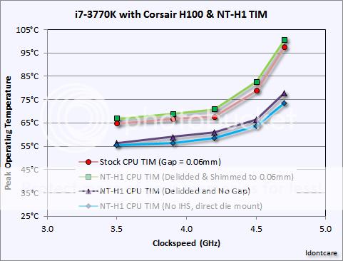
^ for the purposes of your question you are interested in the results between the purple line (with triangles) versus the blue line (with diamonds). That is your "w/IHS vs. w/o IHS" test using the exact same TIM on the CPU (NT-H1).
did anyone point out?
according to the graph. the Intel TIM is superior to NT-H1 TIM.
it is hard to digest that Intel would use top of the line TIM only to do a halfazz job of fitting the IHS.
chances are the stock gap is less than 0.06. so when the NT-H1 TIM is used and the IHS is shimmed back to 0.06. there was not enough die to IHS contact, hence the poorer performance.
Read this post and let us know if you are going to stick with your above stated position on the matter.
pretty hard to dispute that digital caliper. perhap intel's did use premium TIM. better than NT-H1.
so the culprit is the IHS adhesive expanding 0.06 during curing. once the adhesive is removed (delid) and the IHS can sit properly back on the die. the heat issue is cured.
thanks for that info. :thumbsup::thumbsup:
of course reducing the gap will improve the temps, who doesn't know that? but the gap is there on purpose, eliminate the gap and your 22nm chip is dead from stress-induced dislocation growth in a matter of 12-24 months, do we really have to explain Mechanical Engineering 101 stuff to you dolts?"


so , with your mounting , the cpu is barely compressing the socket pins from 0.65mm to 0.6mm , as the cooler hits the alignment pins .
not only that , the other side of the cpu is compressed more , making poor electrical and thermal contact to the heatsink on one side .
i think there is a high probability that your cpu is fried due to poor contact , and not static electricity .
cpu size is a bit more then 40mm square , with alignment pins at the edges of it .I don't think so, since the heatsink doesn't extend to the outer edge of the socket where it could come into contact with the alignment pin.
Those pins are at the edge of the socket nearly under the latching lid of the socket anyway.
hello guys , new member here
i was planning to mount my cpu without the IHS and came to this thread .
IDC , i found a few problems with your mounting , let me explain :
your measurements indicate that the cpu pcb thickness is around 1mm here :
later you posted that pcb + die thickness is around 1.5mm (total cpu , without IHS)
now , there are 2 cpu alignment pins on the 1155 socket , one of them marked here :
i checked the datasheet of the 1155 socket , and guess what , the hight of the alignment pins above the socket floor is 2.1mm
and the socket pins hight is only 0.65mm above the surface .
here are pics from datasheet :
so , with your mounting , the cpu is barely compressing the socket pins from 0.65mm to 0.6mm , as the cooler hits the alignment pins .
not only that , the other side of the cpu is compressed more , making poor electrical and thermal contact to the heatsink on one side .
i think there is a high probability that your cpu is fried due to poor contact , and not static electricity .

Hi sstephan
I can see where you would be left with the impression that the alignment keys are going to be an issue but unfortunately the spec drawings are not giving you the full story.
Note that while the alignment keys are higher in elevation than the neighboring socket perimeter (the side), the four corners of the socket are all at equally high elevations relative to the socket floor.
If the mounting block (be it an H100 waterblock or an NH-D15 HSF) were to compress the CPU into the socket pins to such an extent that the mounting block were to actually come to rest by making contact with the socket then it would so evenly with uniform contact all the way around the chip. It would not be an uneven landing.
However, the top of the PCB is flush with the top of the socket. Meaning the clearance between the top of the CPU silicon die and the highest elevation of the socket is about 0.5mm, not 0.05mm. Plenty of room for the pins to be compressed.
Further still is the issue of over-compression - long before you will "bottom out" the HSF or waterblock on the socket itself the LGA pins become too compressed and begin shorting themselves out, resulting in the system rebooting (or not booting at all).
In practice I found it difficult to get a bad mount with the bare die approach, it just takes time to ensure you are getting the compression right. It is goldilocks, too little and you have a problem, too much and you have a problem. But it is not difficult to get it just right, and lots of people on the internet are able to get it just right.
On the flip side I did manage to unintentionally imbalance the bare-die mount in one of my earlier attempts by getting an extra washer in the mix. That result in the H100 block being uneven by nearly 1mm on one side. Surprisingly I was still able to get a decent mount with good results, and it was only afterwards when I disassembled the bare-die setup (that time) did I realize I had an extra washer on one of the four posts
hey IDC , thanks for replying .
i think you are still missing a few things .
cpu pcb flush with the socket corners - this is correct , intel datasheet provides very accurate information , so no surprise here .
i dont see why you are surprised by that . if you check the datasheet image i proveded , you can see that the hight of the corners of the socket is 1.7mm .
socket pin hight is 0.65mm
so , cpu pcb , sitting on 0.65mm pins = 1mm + 0.65 = 1.65mm , which is approx 1.7mm , as the socket corner (no pressure applied)
thats why you see the cpu flush with the corner .
now the alignment pins hight is 2.1mm +- 0.2mm ,
i measured mine (destroyed socket on old mb , so no pins on socket) and it was 2mm , which is in spec .
uncompressed cpu , sitting on socket hight = cpu thickness + pins = 1.5 + 0.65 = 2.15mm
alignemtnt pin hight = 2.1mm (nominal , mine is 2mm ) , so only 0.05mm pin compression is possible .
my pins are 2mm hight , so i can compress to 2.15 - 2 = 0.15mm , a bit more, but still not enough , not even close .
and , sorry , but there is no such thing as over compressing those pins !
i know this socket too well . intel spec states a MINIMUM compression pressure around 200N , this is done by the socket , closing on the cpu .
thats approx 20Kg of compression force - MINIMUM .
the max is around 400N !
thats why you hear those pins squeaking while closing the socket .
the socket ILM compresses the pins , until the cpu pcb touches the socket pin floor , you can measure that with stock cpu , if you dont beliave me .
btw , max heatsink on cpu pressure allowed is much lower then the socket closing on the cpu .
I finally got around to reading through this fine thread along with IDC's delidding thread. My complements to everyone who contributed to that work. I certainly learned a lot.
I have something I wanted to point out regarding a bare die testing risk that has not been discussed yet but needs mentioning.
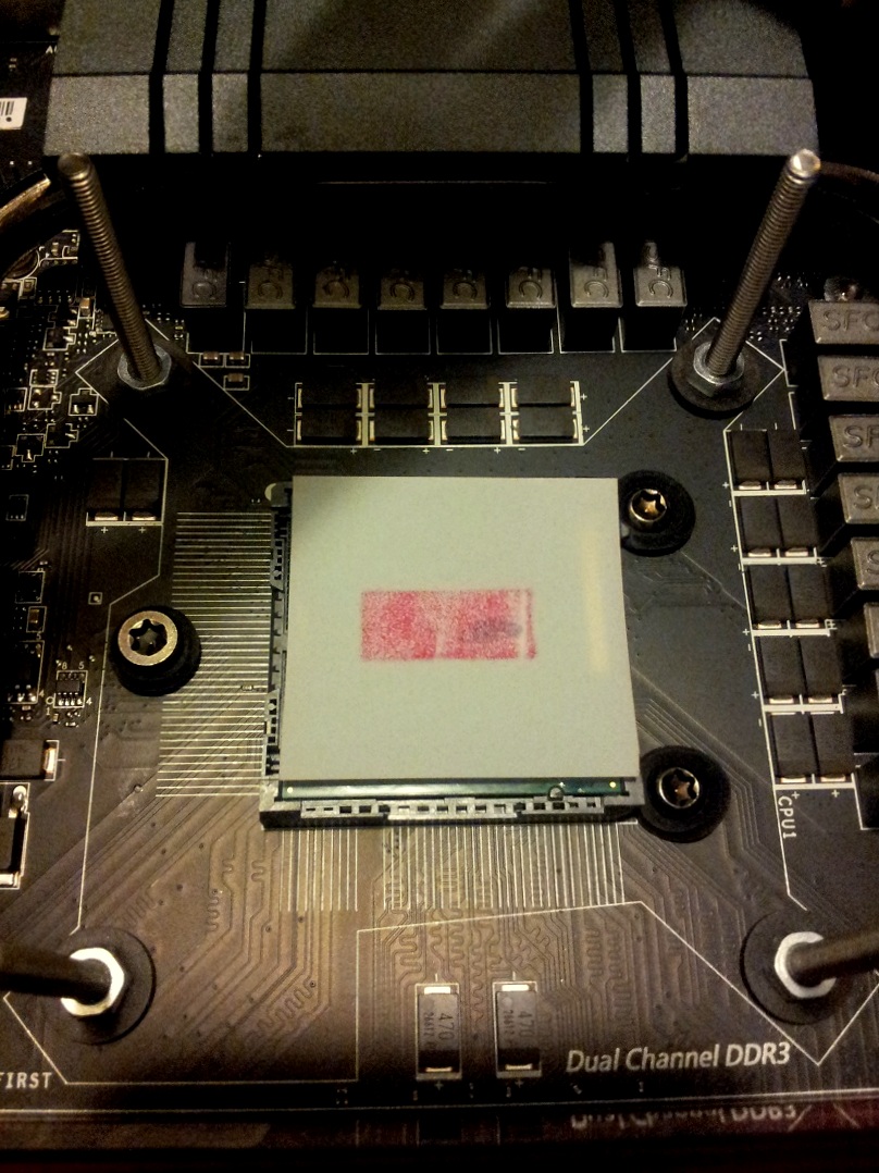
Most of the images I've seen so far with bare die testing have included a copper waterblock connected directly to the bare die. There is a real risk of killing your CPU from copper diffusion through the silicon when doing this. I'll try to explain.
Copper is known to rapidly diffuse through Si and SiO. It is such a risk during the manufacturing process that fabs go to great lengths to segregate equipment and tools which come into contact with wafers with copper on them. I remember being told about an experiment were you place a penny on the surface of a Si wafer and leave it overnight. Copper will be easily detectable on the back side of the wafer such that you can make out the image of the penny. Bad things happen when copper atoms enter the active transistor regions.
There is a nitride layer on the back of the bare die which should act as an effective barrier to copper diffusion. However, if there are micro scratches in the nitride layer it could open up a pathway for copper diffusion to occur. IC Diamond in particular seems a risky compound to use. I believe its possible this could have been what killed IDCs 3770K.
2 major failure points for thermal compound are Pump Out which occurs with thermal cycling, the expansion and contraction of the joint literally pumps liquid/compound out from between the mating surfaces.
The other is Bake Out where a high heat load dries out the compound and leaves voids in the joint as a result and while the remaining liquidless hardened compound works to a degree until it is eventually delaminated from the contact surfaces with thermal cycling