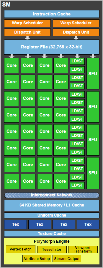
The first stage begins by fetching vertices from a global vertex buffer. Fetched vertices are sent to the SM for vertex shading and hull shading. In these two stages vertices are transformed from object space to world space, and parameters required for tessellation (such as tessellation factor) are calculated. The tessellation factors (or LODs) are sent to the Tessellator.
In the second stage, the PolyMorph Engine reads the tessellation factors. The Tessellator dices the patch (a smooth surface defined by a mesh of control points) and outputs a mesh of vertices. The mesh is defined by patch (u,v) values, and how they are connected to form a mesh.
The new vertices are sent to the SM where the Domain Shader and Geometry Shader are executed. The Domain Shader calculates the final position of each vertex based on input from the Hull Shader and Tessellator. At this stage, a displacement map is usually applied to add detailed features to the patch. The Geometry Shader conducts any post processing, adding and removing vertices and primitives where needed. The results are sent back to the Tessellation Engine for the final pass.
In the third stage, the PolyMorph Engine performs viewport transformation and perspective correction. Attribute setup follows, transforming post-viewport vertex attributes into plane equations for efficient shader evaluation. Finally, vertices are optionally “streamed out” to memory making them available for additional processing.
On prior architectures, fixed function operations were performed with a single pipeline. On GF100, both fixed function and programmable operations are parallelized, resulting in vastly improved performance.