Delidded my i7-3770K, loaded temperatures drop by 20°C at 4.7GHz

Page 21 - Seeking answers? Join the AnandTech community: where nearly half-a-million members share solutions and discuss the latest tech.

Phynaz

Lifer
Mar 13, 2006
10,140
819
126
Wow, it's amazing what a difference that gap that is half the thickness of a sheet of paper makes, even when it's filled with a TIM.

No flaming from me on your conclusion, it's mostly what I expected. What I didn't expect was how small the gap was.

Does anybody have any data on how flat heatsink surfaces are? I curious to know how big of gaps are getting filled with TIM doing standard mounts.
 

ehume

Golden Member
Nov 6, 2009
1,511
73
91
Hmm. It seems that for a heatsink to sit directly on the CPU, the contact face should be should be small enough to fit inside the socket. Could an IHS-sized patch on the heatsink contact face be built up with solder?
 

Anth Seebel

Junior Member
Aug 22, 2012
14
0
0
Well some CL Liquid pro arrived couple days ago so I got to work immediately to install it as I was curious about the results of this TIM. Also bought some Permatex black silicone adhesive to glue IHS back on so that IHS wouldn't slide when I installed cpu into socket.

So after wetting both the die and under IHS with liquid pro I placed small blobs of adhesive in the corners and just left it for about 30mins. That is all the time it took for the cpu to be strong enough to handle and the IHS not be affected by gravity (upright case). Plus I wanted the pressure of the waterblock mount and retention socket to be applied as the glue cured to ensure the smallest gap possible between the IHS and die.


My results summary:
(From MX4 to CL Liquid pro under IHS)

  • 9-10C improvement at load
  • heat delta (difference between idle temp and load temp) from ~30C to ~20C
  • before: 4.5ghz load temp 57C, after: 4.8ghz load temp 55C (ambient 17C)

Before: MX4 under and on IHS (ambient 17C).
b4liquidpro_zpsa9ec7fc7.jpg


After: CL liquid pro under IHS, Gelid gc-extreme on IHS (ambient 17C)
afterliquidpro2cambient_zps1b8d81dc.jpg


Update on this: the reason I failed to upload the results as promised weeks ago is that I can't find my camera which has all the photos on it. I've made numerous efforts to find the camera but all with no success. :(

In the meantime I did another test using a simple sheet of paper (0.13mm thick per the digital calipers) cutout as a shim.

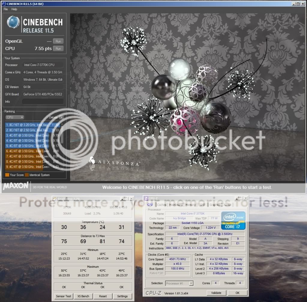
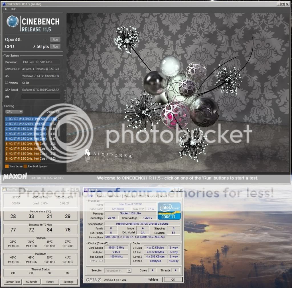
The paper shim lifted the IHS off the CPU such that the final stack height was 4.24mm. You'll recall from post #77 that the original stack height was 4.21mm. So at this point the IHS is making a gap to the CPU of 0.09mm versus the original gap of 0.06mm.

Unsurprisingly the temperatures are really bad, worse than stock before delidding when the CPU had a 0.06mm gap and was using the stock TIM.

My observations after having made numerous attempts to shim the IHS off of the CPU is that the CPU temperature is wildly dependent on the gap between the CPU and IHS and it doesn't really matter what TIM I use (I tried IC Diamond as well).

Based on these multiple efforts, my anecdotal conclusion on delidding my 3770k is that the stock CPU TIM that Intel uses is probably just as good as NT-H1 or AS5 in terms of thermal conductivity. I don't believe the stock TIM is the reason Ivy's temps are so high.

I now believe the problem is entirely due to the stock gap that exists between the IHS and the CPU, for my CPU that gap was 0.06mm in stock configuration. Removing the IHS adhesive allowed me to close this gap to basically zero, and for that reason alone my temperatures dropped as dramatically as they did IMO.

I am reluctant to post this because I know it flies in the face of conventional wisdom which is that "Ivy's temps are bad because Intel went and used cheap TIM instead of good quality solder". But based on my efforts and testing to date with my CPU I no longer believe this to be true and I feel I should at least attempt to set the record straight. (but I know I'm gonna be flamed for speaking out about this because it really isn't what folks want to hear)

I am now firmly convinced the sole reason Ivy has elevated temperatures is because of the gap that exists between the CPU and the IHS, a gap that must be filled in with TIM and regardless what TIM I use to fill that gap my temps are horrible unless I take away my shims and let the IHS rest solidly directly on the die itself.

It is not the TIM that is cheap, it is that so much of it is required between the CPU and the IHS in the first place because of the gap.

The only question that remains in my mind is why did Intel leave such a large gap between the IHS and the CPU? Is it for thermal stress cycling reasons? (seems unlikely given that the same CPU's are sold without IHS's for laptops)

The only reason I care to know why Intel left such a large gap under the IHS on the desktop chips is because I don't want to unwittingly destroy my IB from thermal cycling if that is the concern. We'll probably never know the answer.

After changing the intel TIM to MX4 weeks ago, I only noticed a 3-5C drop where others where getting bigger gains. My conclusion was that the intel TIM wasn't as bad as people were making out and that the variances in the way the IHS was glued on and variances in the IHS itself were causing gaps between die and IHS.

As we know, when you remove the glue the gap is minimised (IHS sits on the die and can spin - not touching pcb). So intel perhaps using too much glue and/or letting the glue dry while the IHS no longer completely sits on the die is what Im thinking. After fixing the issue of the gap and replacing the TIM with something close to solder (liquid metal) these chips are given a far more optimal thermal package, unlike the default sub-optimal thermal package. I wonder if the decision to use paste and not solder on the die was made from a technical or economic (not make their other products look bad) standpoint?

EDIT:
After using the black adhesive it got me thinking further. The adhesive is quite 'runny' or 'thin' , it is easily squeezed out when the IHS is placed in the pcb. If intel is using similar stuff, which it looks like they are, then the glue itself is unlikely causing the gap. I think it is the type/amount of paste they use and variances in how flat the under-side of the IHS is. The heat paste they use and even stuff like MX4 is quite thick , very thick and much less thermal transfer properties than solder), this alone would degrade thermal transfer by a significant amount. When they assemble the cpu the paste is applied to the die and the gap will be determined by how the paste is applied (how even across the die), the amount of paste used and the how flat the underside of the IHS is parallel to the die. Be interested to hear others thoughts on this.
 
Last edited:

BonzaiDuck

Lifer
Jun 30, 2004
15,699
1,448
126
It won't. The CPU die is ridiculously thin. Really. Even I was a bit taken aback by how thin the die was when I popped off the lid.

If you grind down your IHS such that it is the same height as the CPU then your IHS will be reduced to a metal ring that stands only 140um tall.

To go bare-die direct contact you will have to remove the retention mechanism. I'm not sure if all retention mechanisms are designed the same from mobo to mobo but the one on my MIVE-Z looks to be easily removable with a simple Allen key wrench.

I intend to do this but first I have to get new bolts for my H100 as the standoff height of the H100 bolts are way too high (it would not make contact with the die if I took the IHS out of the picture).

When we had that discussion (much earlier in this thread), I don't think I mentioned another possibility: If the HSF-base is thick enough so that damage won't occur to the heatpipes or welds/solder that bond them to the base, it might be possible to grind down a "rectangular donut" of the heatsink base, leaving a smaller square of the heatsink-base to fit inside the retention mechanism. But again -- just to get lower temperatures on an Ivy Bridge, this doesn't seem like a good effort-to-outcome ratio.

Of course, at that point, one would've taken "unwarrantied" ownership of the ~$300+ processor, so it wouldn't matter so much for doing the same with a $60 heatsink. Here, I'm assuming that some heatsink-bases have enough material thickness in the base to make such a thing possible -- an assumption that would need to be proven with respect to this or that heatpipe cooler. Those with "direct-touch" design would be totally unfeasible for that strategy.

Finally, you might be the first to tell me that such a solution wouldn't work with a water-block, which might not have enough thickness to go that route.

If the only way to make direct contact involves removing the latching mechanism, then that's the only option, I think . . .

Anth Seebel said:
My results summary:
(From MX4 to CL Liquid pro under IHS)

  • 9-10C improvement at load
  • heat delta (difference between idle temp and load temp) from ~30C to ~20C
  • before: 4.5ghz load temp 57C, after: 4.8ghz load temp 55C (ambient 17C)

Basically, some of these results -- including yours -- suggest that it's "not just the gap between the IHS and die," but the choice of TIM. In your case, part of our comparison between Intel's own (previous generation ) indium-silver fluxless-solder and the Liquid Pro options still includes some speculation. If it works and doesn't cause processor damage in the short-term, then I'd personally "guess" that it wouldn't cause damage in the long-term, either. But . . . there's also an aspect of speculation in my "guess."
 
Last edited:

rge2

Member
Apr 3, 2009
63
0
0
Intel has quoted their tim1 as 3-4 w/mk as late as 2008 (below in white paper quote), and unlikely to have changed much given transition to solder for higher tdp cpus. Similar specs have been measured with typical user paste tim.

The silicon copper laden die conducts heat at 125w/mk, copper ihs 400 w/mk. No wonder why white papers state 50% temp gradient is in interfaces, most in interface tim1. 3-4 w/mk is going to be a huge roadblock between 125w/mk and 400 w/mk materials. And the wider this area, ie thicker bondline will have major impacts.

That being said replacing intels polymer tim1 ~3-4w/mk with typical liquid metal (higher bulk thermals, lower contact resistance, thinner bondline than polymers/pastes) should yield significantly better results.

Replacing intels tim1 with say mx4, you may be replacing with similar thermals, and reducing gap may be biggest factor there, plus sometimes automated tim is less than ideal application, or some of newer tims may be marginally better than intels with marginal results, liquid metal aside.

Also those getting higher reductions may have thinner/more convex IHS centers and larger gaps vs those seeing lower (intel lists their IHS tolerances in one of there old white papers, I think I referenced it in Realtemp thread on xtreme when inserting thermocouple in IHS for testing for Realtemp...couldnt find it on search. Plus dont know if still there.) I wish I could remember the tolerances/variance or find them...would be interesting to see.


http://download.intel.com/technolog...ials_Technology_for_Environmentally_Green.pdf
The primary role of the IHS is to spread the heat out evenly from the die and to provide a better bondline control of the interface material. This can be achieved by increasing the area of the IHS and by using a high thermal conductivity thermal interface material with low interfacial resistances. In order to meet thermal dissipation targets, Intel introduced polymer thermal interface materials (PTIM) initially with 3-4 W/moK bulk thermal conductivity and then successfully transitioned to Pb-free solder-based thermal interface material to meet the ever increasing demand for thermal cooling capability as shown in Figure 16 [5]. The introduction of Pb-free solder-based TIM materials posed significant integration challenges. The STIM needed to relieve the mechanical stress caused by CTE mismatch of the integrated heat spreader lid and the silicon die and to minimize stress transfer to the silicon die during thermal cycling [6]. The thermal conductivity and the mechanical compliance requirements resulted in the development and qualification of low melting temperatures (157oC Tm), low mechanical yield strength (4-6 MPa), and relatively high thermal conductivity (~87 W/moK) pure Indium (In) metal for STIM applications.
 
Last edited:

C.C.

Member
Aug 21, 2012
28
0
0
When we had that discussion (much earlier in this thread), I don't think I mentioned another possibility: If the HSF-base is thick enough so that damage won't occur to the heatpipes or welds/solder that bond them to the base, it might be possible to grind down a "rectangular donut" of the heatsink base, leaving a smaller square of the heatsink-base to fit inside the retention mechanism. But again -- just to get lower temperatures on an Ivy Bridge, this doesn't seem like a good effort-to-outcome ratio.

Of course, at that point, one would've taken "unwarrantied" ownership of the ~$300+ processor, so it wouldn't matter so much for doing the same with a $60 heatsink. Here, I'm assuming that some heatsink-bases have enough material thickness in the base to make such a thing possible -- an assumption that would need to be proven with respect to this or that heatpipe cooler. Those with "direct-touch" design would be totally unfeasible for that strategy.

Finally, you might be the first to tell me that such a solution wouldn't work with a water-block, which might not have enough thickness to go that route.

If the only way to make direct contact involves removing the latching mechanism, then that's the only option, I think . . .
BD,

I personally feel that the removal of the stock retention bracket is the proper way to go..It literally takes about 30 seconds to remove the three screws..

That being said, I offer you a challenge..I am willing to give you a Tuniq Tower 120 HSF, which has 6 heatpipes, but has a "base" in between them and the IHS..You can take this HSF and grind the base down to your liking..I certainly don't care if you destroy it, but I actually hopes it will work out since you don't seem to be a WC guy..

The only catch is that you need to get a MB that supports both socket 1155 and Socket 775 mounting points, since the TT 120 didn't exist back then..The good news is that one of the cheapest/best performing MB's is the ASRock Z77 Xtreme 4, which has both..I love this board, and Anantech gave it very high remarks, with it beating out every other Asus/GB etc board they tested in many areas..

If you wanna give it a shot, just let me know.
 

BonzaiDuck

Lifer
Jun 30, 2004
15,699
1,448
126
BD,

I personally feel that the removal of the stock retention bracket is the proper way to go..It literally takes about 30 seconds to remove the three screws..

That being said, I offer you a challenge..I am willing to give you a Tuniq Tower 120 HSF, which has 6 heatpipes, but has a "base" in between them and the IHS..You can take this HSF and grind the base down to your liking..I certainly don't care if you destroy it, but I actually hopes it will work out since you don't seem to be a WC guy..

The only catch is that you need to get a MB that supports both socket 1155 and Socket 775 mounting points, since the TT 120 didn't exist back then..The good news is that one of the cheapest/best performing MB's is the ASRock Z77 Xtreme 4, which has both..I love this board, and Anantech gave it very high remarks, with it beating out every other Asus/GB etc board they tested in many areas..

If you wanna give it a shot, just let me know.

For being retired, dabbling in political activism, watching TV, and other pursuits -- modding and OC'ing has been "my hobby." I was seriously thinking to enter the water-cooling arena, and going back some six years to posts I made here and some research I'd done, was looking at some plans for "Rube Goldberg" contraptions like an evaporative-cooler "chiller" rig, etc. But when the processor TDPs started coming down, I just decided to "KISS" and stick with heatpipes.

There's a machine-shop near here that's still in business. Despite the tools that I have, I'd probably take such a project to them. But like the thoughts I had about magnificent WC configurations, I'm not sure I'm eager to follow that path.

If removing the bracket is just a matter of the screws, then I'd think it's reversible, and that's probably the best "KIS" solution.

That being said, did IDC note that he had to mod the standoffs for his waterblock? I'm not sure such would be required for various heatpipe coolers; they're just spring-loaded devices, and you only have to be careful getting them to sit right while you slowly torque down the four screws round-robin fashion.

I'm thinking -- if one wanted to go that way -- grinding down the IHS to make a "square-donut" shim to stabilize how the heatsink or waterblock sits on the die might offer additional benefit. Of course, like the suggestion we were discussing, that's a lot of work. I don't see why you couldn't fashion one out of a piece of Lexan, and the grinding would be . . . easy.
 

anikhtos

Senior member
May 1, 2011
289
1
0
hahahah i almost get baned from the forum for criticizing intel and ivy bridge for being too hot
only a few months to be right with posts like this 20 c lower
i want to thank the forum and intel big pockets for being able to buy forums like this and keep the criticism non existence
the forum is so biased in all the topics about amd cpu much harsher words are used but it is allowed
as it seems virgin intel has the money to pay to remain virgin
after all someone must make a living even if that means being biased in a forum that is supposed to be unbiased
thank you
now you can ban me
and delete my message as you have done in the past
after all i talked against intel.
may i should be executed in the square to make an example out of me.

This is the wrong forum for this, and you know it. Discussions about forum moderation belong in Moderator Discussions, not in the tech forums.
-ViRGE
 
Last edited by a moderator:

Ferzerp

Diamond Member
Oct 12, 1999
6,438
107
106
I remember that nutter. Guess his ban expired. Didn't understand the difference between temperature and heat if I recall correctly.
 
Last edited:

hachre

Junior Member
Sep 4, 2012
5
0
0
IDC, thanks for your update, somehow the forum failed to inform me of new posts so I only saw it now :) Very interesting that it seems to be all about the gap!
 

Idontcare

Elite Member
Oct 10, 1999
21,118
58
91
IDC, thanks for your update, somehow the forum failed to inform me of new posts so I only saw it now :) Very interesting that it seems to be all about the gap!

Yeah it really does seem to be all about the gap after all, and the focus on the TIM itself turned out to be more of a red herring in this argument.

But it still doesn't anwer the question - why the gap?

I'm leaning towards believing the theory posited by other members which is that the gap has always been there in Intel chips but because they historically filled the gap with metal solder the gap itself was not a thermal barrier of any sort.

Once they replaced the solder with something far less thermally conductive then it became an issue. The only way to correct that is to eliminate the gap (what delidding essentially accomplishes) or replace the TIM with liquid metal TIM (something Intel thought was a bad idea for IvyBridge CPUs).
 

BonzaiDuck

Lifer
Jun 30, 2004
15,699
1,448
126
Yeah it really does seem to be all about the gap after all, and the focus on the TIM itself turned out to be more of a red herring in this argument.

But it still doesn't anwer the question - why the gap?

I'm leaning towards believing the theory posited by other members which is that the gap has always been there in Intel chips but because they historically filled the gap with metal solder the gap itself was not a thermal barrier of any sort.

Once they replaced the solder with something far less thermally conductive then it became an issue. The only way to correct that is to eliminate the gap (what delidding essentially accomplishes) or replace the TIM with liquid metal TIM (something Intel thought was a bad idea for IvyBridge CPUs).

Either that, or accept the less-than-optimal thermal conductivity between IHS and die, get a decent to good IB chip, and then implement more than adequate WC or even chilled WC. What I get from you and other posters who've moved forward with this problem: you reap some improvements in both voltage and speed by lowering the temps.

What about dqneil's experience with the diamond paste? I thought his temperatures were pretty stellar for a 4.5Ghz over-clock . . . .
 

know of fence

Senior member
May 28, 2009
555
2
71
Intel certainly has to use special low melting-point solder to attach the spreader to electronics, but soldering the now separated lid to the heat sink should be easy enough with a blowtorch and regular plumbing solder wire. This soldering method uses the capillary force of molten tin-solder to fill the tiny gap between two heated metal surfaces. Surely, there are DiY guys, who know a thing or two about copper plumbing!

If this doesn't work, all that is lost is a useless lid (maybe heatsink as well), if it works you have the original spacer, which fits perfectly into the cpu fixture and you basically replaced one layer of TIM with very thin solder.

[edit] Just to be clear and this is as somewhat unusual idea which requires a little "curing time" to settle in, I'm talking about a method of soldering the delidded IHS to your cooling solution of choice, a heatpipe air cooler or a custom waterblock. It would makes sense if you want to use the IHS as an installation help, instead of something like those little foam circles that the first 1GHz CPUs used back in the day.
http://upload.wikimedia.org/wikipedia/commons/d/df/KL_AMD_Athlon_XP_Thunderbird.jpg
Disposing of the IHS, and mounting the cooler directly to the chip is obviously better, than re-building the original double decker sandwich.
 
Last edited:

kelco

Member
Aug 15, 2012
76
0
0
I have one 939 lidded amd I could practice on... Wouldnt mind trying it on the 8150 if it went well.
 

Idontcare

Elite Member
Oct 10, 1999
21,118
58
91
Why would anyone re-attach their IHS with solder? That baffles me.

If you want superior cooling performance you'll mount your die in some direct-contact fashion with your water block.

Think about it - you've attacked your $300 CPU with a razor blade, risking personal injury no doubt and accepting the possibility of total loss of your CPU in the process, just to get the lid off in the first place.

Are you really going to find the effort of removing three bolts (no risk of loss of limb involved) so you can remove the socket retention clasp on your <$300 mobo (which is also in no risk of damage from this stage of the mod) as being an unacceptable next step in the process?

And why would you re-attach the IHS with solder at this point? The only reason to put the IHS back on the die is because you are worried about the die cracking without the aid of the IHS diffusing the stress of the HSF block.

And if that is your concern and motivation for putting the IHS back on then why on earth would you expose your silicon die to the tortorous thermal differentials of being room-temperature on the PCB/package/CPU side and being ~200C on the IHS and liquid solder side?

If your silicon was ever going to go pop-crack-snap it is at that moment in time when it first heats up nonuniformally to 200C at the solder interface, or when that 200C IHS cools down and physically shrinks at a rate far faster than that of the CPU die to which it is now physically attached - transferring all that compression strain straight through the die and into the flip-chip bumps holding the die onto the PCB package in the first place.

If you succeed in reattaching your IHS with solder then at best your cooling efficiency will be close to, but never as good as, that of the people who just direct-die cool their CPUs but you will have taken your CPU on one hellish journey that even Intel won't dare take it on.

But at least you know Intel knows their chips can survive direct-die cooling because that is exactly how these same chips get cooled in laptops.
 

Yuriman

Diamond Member
Jun 25, 2004
5,530
141
106
IDC, I'm very tempted but also concerned with the idea of attaching my waterblock bare-die. I have a Swiftech Apogee GT:

swiftech31smalloj0.jpg

Image courtesy of google.

Back when I was watercooling bare-die chips, the hold-down mechanism typically pressed directly on the center of the waterblock. The Apogee however has its mounting holes very far from the die, and I worry that it would be extremely easy to tighten it down unevenly and crush a corner or even a side of the CPU. Add to that the fact that I'm using the S775 mounting holes on my ASRock Z77 Extreme4 - they're not perfectly square with the CPU, but rather slightly rotated so it can have both 1155 and 775 mounting holes.

I don't think I would need to take off the socket retention mechanism as the waterblock has a raised square in the middle where it makes contact with the IHS (and would probably not hit the bracket) but I don't suppose the bracket actually does anything if you don't have an IHS for it to press down on?

I'm thinking I would be safer if I changed out the short bolts with longer bolts + a spring.

What are your thoughts?
 
Last edited:

Idontcare

Elite Member
Oct 10, 1999
21,118
58
91
IDC, I'm very tempted but also concerned with the idea of attaching my waterblock bare-die. I have a Swiftech Apogee GT:

swiftech31smalloj0.jpg

Image courtesy of google.

Back when I was watercooling bare-die chips, the hold-down mechanism typically pressed directly on the center of the waterblock. The Apogee however has its mounting holes very far from the die, and I worry that it would be extremely easy to tighten it down unevenly and crush a corner or even a side of the CPU. Add to that the fact that I'm using the S775 mounting holes on my ASRock Z77 Extreme4 - they're not perfectly square with the CPU, but rather slightly rotated so it can have both 1155 and 775 mounting holes.

I don't think I would need to take off the socket retention mechanism as the waterblock has a raised square in the middle where it makes contact with the IHS (and would probably not hit the bracket) but I don't suppose the bracket actually does anything if you don't have an IHS for it to press down on?

I'm thinking I would be safer if I changed out the short bolts with longer bolts + a spring.

What are your thoughts?

The socket bracket won't help with anything, you really may as well remove it.

Replacing the bolts and using springs is the way to go. That is what I did when I delidded by GTX460 and that worked out just fine. (see pics in post 33 specifically)

I just got my bolts for putting my H100 straight to the die. Plan to do those tests soon.
 

Yuriman

Diamond Member
Jun 25, 2004
5,530
141
106
Finally popped my lid:

img20120929233651.jpg


img20120930000224.jpg


I used the method you first mentioned - placed the heatspreader back over the CPU and locked it in place with the retention bracket. I'm using Phobya HeGrease, which reviewed pretty well in comparison to other non-metal TIM's.

Unfortunately, my temps did not improve, I guess they're something else causing my high temps.

Pre-pop Prime Small FFT temps:
4.4ghz - 78c (1.192v)
4.6ghz - 89c (1.304v)

Post-pop Prime Small FFT temps:
4.4ghz - 79c
4.6ghz - 94c

I remounted and had no significant change in temps. Obviously the paste hasn't had time to settle in but I'm not expecting any miracles. I'm going to pull it apart in a bit and check the flatness of the heatspreader and waterblock. If nothing's amiss there, I'll pull my waterblock apart and make sure my jets are oriented properly.

Any thoughts?

EDIT: Looks like (the top of) my heatspreader is pretty concave, will grab some sandpaper tomorrow. I wonder if the underside is just as bad?
 
Last edited:

Idontcare

Elite Member
Oct 10, 1999
21,118
58
91
Finally popped my lid:

img20120929233651.jpg


I remounted and had no significant change in temps.

Did you remove all the IHS adhesive (the black stuff) from both the PCB and the IHS?

When you have no CPU paste on the CPU or the IHS, can you freely spin your IHS? (meaning it is not making contact with the PCB)

The next thing to be careful about is on the PCB where the black rectangle is with the writing on it, that is a raised area. Do not let your IHS slide up onto that when securing the socket retention bracket (you will notice the bracket pushes the IHS in the direction of the latch).

If the IHS slides up onto the bevel of that black rectangle then you will be creating a larger gap between the IHS and the CPU.

The other thing to check is the amount of TIM paste you are using and the type. If you have access to any other type you should at least try it to see if it makes a difference.

With my 3770k, by far and away the one thing that changes my operating temps the most is the gap between the IHS and the CPU.

The only time I see my 20C decrease in temps is if I let the IHS make direct contact with the die (with TIM inbetween of course). As soon as I do anything to lift the IHS off of the CPU, using metal shims or paper shims, the temperatures go crazy high.

So my advice to you is to get to know the gap between your CPU and IHS and figure out what it will take for you to eliminate it.

My next tests wiil be testing without the IHS. First though I have to repair my H100. I used that IC Diamond stuff for one test with the IHS and holy crap if it didn't corrode the bejesus out of the copper surface on my H100 and my IHS. It also scratched the CPU silicon die itself.

I'm rather pissed about that because I had my reservations and yet the IC diamond guy convinced me it wouldn't happen. But there it is, a big old scratch right on my chip and now the materials science education in me tells me exactly what that crack is going to do to the rest of my chip :( I've no one to blame but myself though, I knew better but I did it anyways.
 

RussianSensation

Elite Member
Sep 5, 2003
19,458
765
126
Not sure if this was posted in this thread, but there is a 21 min video of a guy delidding his i5 3570K with a step-by-step guide. The delidding process took less than 10 minutes and required only a thin sharp blade and some patience. No torches necessary :). The user then reapplied TIM in the form of MX-2 and put in the original IHS on top to make sure the HR-02/Macho heatsink didn't crush the die without shims:

Fixing Ivy Bridge CPU temps: IHS removal
 
Last edited: