-
We’re currently investigating an issue related to the forum theme and styling that is impacting page layout and visual formatting. The problem has been identified, and we are actively working on a resolution. There is no impact to user data or functionality, this is strictly a front-end display issue. We’ll post an update once the fix has been deployed. Thanks for your patience while we get this sorted.
You are using an out of date browser. It may not display this or other websites correctly.
You should upgrade or use an alternative browser.
You should upgrade or use an alternative browser.
Delidded my i7-3770K, loaded temperatures drop by 20°C at 4.7GHz
Page 14 - Seeking answers? Join the AnandTech community: where nearly half-a-million members share solutions and discuss the latest tech.
ehume
Golden Member
I wonder if the thermal cycling problem comes from having an IHS that has a fixed relationship with the pcb. I know that the corners of an IHS can be an issue. With my i7 860, for example, I see corner scars on each heatsink I use, which limits the amount of pressure I can bring to bear.
I wonder what would happen if the IHS were simply curved at its edges, and rested on the cpu rather than the pcb, if the edges of the ihs were sealed with an elastic material rather than metal walls. Since the heatsink or waterblock is held to the ihs essentially by screwed-in springs, any heat cycling would simply be adapted-to by the spring-mounted cooling surface.
I wonder about this because a 'floating' ihs would solve the thermal cycling issue and allow Intel to solder their chip to the ihs, which would act as it always has -- to spread the heat for transfer to the cooling block.
Now IMO this is a fairly obvious response to a cycling problem -- docks use it all the time. So why didn't Intel use it?
BonzaiDuck
Lifer
All I know is both NT-H1 and AS5 don't last long for me. I keep reducing the amount. I'm still hoping I'm causing it instead of having a processor that I have to re-apply paste to every few weeks 😉
"Hope AFTER change" -- For your sake, for IDontCare and others -- I "hope" there is some.
If there weren't an "opportunity cost" to building my IB rig right now with no forethought to the risk, I'd be in the same boat.
And I HOPE . . . we will find a solution that doesn't "evaporate" after a few weeks . . .
Someone else here (on this thread) had (supposedly) applied the Liquid Ultra. Oh . . . it was "Lesd." Also, another person, I think . . . I hope they stay "plugged in" to inform us whether their stunning projects turned into disasters. And I hope that their projects don't turn into disasters.
Let's just say it's interesting to test and have a 66C (4.4Ghz @1.224V in CPU-z) maximum in 15 minutes of IBT, and then in a random length of time end up with temps 20C higher than that.
I don't know how long things last. I usually notice when I start hearing the CPU fans getting louder than they are when I first set it up. I'll then do IBT, and immediately have temps in the 80's.
I don't know how long things last. I usually notice when I start hearing the CPU fans getting louder than they are when I first set it up. I'll then do IBT, and immediately have temps in the 80's.
dqniel
Senior member
Let's just say it's interesting to test and have a 66C (4.4Ghz @1.224V in CPU-z) maximum in 15 minutes of IBT, and then in a random length of time end up with temps 20C higher than that.
I don't know how long things last. I usually notice when I start hearing the CPU fans getting louder than they are when I first set it up. I'll then do IBT, and immediately have temps in the 80's.
I haven't had that issue yet with IC Diamond and I've done hours and hours of burn-in. Fingers crossed.
I haven't had that issue yet with IC Diamond and I've done hours and hours of burn-in. Fingers crossed.
I'm talking weeks/months, not hours.
mrob27
Member
The concern we have is that of crack propagation. (highly recommend checking out the link)
That link is broken, but works if you remove "forums.anandtech.com".
Corrected link: Failure of Silicon: Crack Formation and Propagation
IDC, those are some great places to eat..One of my newer favorites is De Lazy Lizard..They have fillet mignon cheese-steak that is out of this world! Truly the best I have ever had!
I have been thinking about the issue I mentioned being concerned about (the IC Diamond dripping down onto my gpu)...Is the IC Diamond more of a paste, or is it a liquid gel?
If it is a gel, then I was thinking about making an extremely thin square rubber gasket..I would make it just a hair taller then the die itself, so that when I tighten the cpu block down, it would compress a tiny bit and make a seal..Any thoughts?
BonzaiDuck
Lifer
I haven't had that issue yet with IC Diamond and I've done hours and hours of burn-in. Fingers crossed.
I'd say, keep running occasional burn-in tests, just to heat things up for a half-hour or so ever couple days, and "keep your iron in this fire" of the de-lidding thread.
The diamond paste could turn out to be a good bet.
C.C. said:If it is a gel, then I was thinking about making an extremely thin square rubber gasket . .
C.C. -- it's a very thick paste. Some other company (don't remember the name now) had produced a grease or oil much like other TIMs, with a 10% diamond loading. The IC Diamond is more like 90% loading.
It's thick enough that one might use a razor-blade to spread it, and still be frustrated that attempts to spread it tears holes in the layer (which would leave air-pockets). It takes a little longer with attention to these things, but not a particularly daunting task. I would spread some on a heatsink base in a square patch to match the IHS placement, and then put another layer on the IHS, or just a rice-grain in the center of it.
The amount of particulate and the observation that the bead of surplus paste dries into a firm, rubbery blob suggests to me that you may not need to make a gasket. Once a layer of the particulate is trapped between the IHS and CPU die, those particles aren't going to "squeeze out." If it did, it would indicate the gap between the IHS and die is too wide -- perhaps allowing the creation of "voids."
The fact that dqneil has at least got it "working" is a hopeful sign . . . to me, anyway . .
AFTERTHOUGHT: Just my recommendation to any others using the diamond paste: spread it on the underside of the IHS. You might use a few "mini-blobs" of the stuff on the die itself -- I just wouldn't attack the die with a razor-blade. Also, I would imagine in this particular case that a surplus of the stuff is not going to give you sub-optimal results. It's just a little extra "expense."
Last edited:
tweakboy
Diamond Member
THis turned out to be a great informative thread.
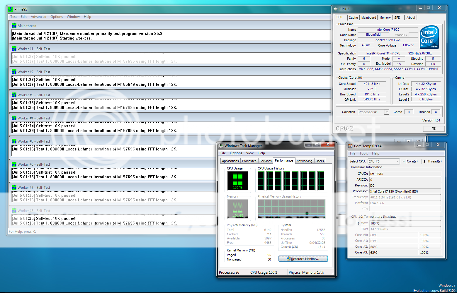
Good job with your TIM experience. 70's c is way higher then what intel wants you to run it. Intel says 50's to 60's is great temp OC or not. Your almost at 80c and your delided lol. Also your vcore is 1.2v ? Man I would take that to 1.4v and OC to 6Ghz
Can these chips run @ 6Ghz under water of course.
BD, thanks for the info..I am not using the IHS, my waterblock is mounted directly to the die of my 3770K..That being said, since you stated it is indeed a thick paste, I am going to order some when I get paid on the 3rd..I will report back once I have some and will do whatever testing vs the Arctic Cooling MX-2 that I currently have..The amount of particulate and the observation that the bead of surplus paste dries into a firm, rubbery blob suggests to me that you may not need to make a gasket. Once a layer of the particulate is trapped between the IHS and CPU die, those particles aren't going to "squeeze out." If it did, it would indicate the gap between the IHS and die is too wide -- perhaps allowing the creation of "voids."
I am not sure where you got your information, but you could not be more wrong on every point you made..THis turned out to be a great informative thread.
Good job with your TIM experience. 70's c is way higher then what intel wants you to run it. Intel says 50's to 60's is great temp OC or not. Your almost at 80c and your delided lol. Also your vcore is 1.2v ? Man I would take that to 1.4v and OC to 6Ghz
Can these chips run @ 6Ghz under water of course.
1. "70C" is NOT way higher then what Intel recommends..The TJMax is over 100C, which means the chip is designed to safely function @ temps up to this point..
2. 1.4V is A LOT of voltage to put into one of these cpus..I am not saying they can't handle it with proper cooling, but these chips are designed to run with much lower voltages then previous designs, including the recent Sandy Bridge cpus..
3. These chips will NOT run @ 6Ghz, unless you are using phase change or Liquid Nitrogen to cool them...They top out @ 4.8Ghz, 4.9-5Ghz if you are lucky..
dqniel
Senior member
I'd say, keep running occasional burn-in tests, just to heat things up for a half-hour or so ever couple days, and "keep your iron in this fire" of the de-lidding thread.
The diamond paste could turn out to be a good bet.
Will do!
BonzaiDuck
Lifer
Will do!
Others may differ, but two weeks -- if no noticeable change in same-test load temperatures at same room-ambient -- sounds good so far . . .
Let's see what happens in a month, or two weeks hence. It's your choice of you want to expand the observations to a larger, more frequent block sample or times series.
BonzaiDuck
Lifer
I've been testing mine daily. Right now, with similar ambient, my temps have actually dropped ~3C since the last application.
Did you reapply AS5? Hope you can minimize your further maintenance until we're more certain of better options here . . .
Jadow
Diamond Member
I just got my 3770k today and am running stock HSF with no thermal compound.
At max load encoding a blu ray at around 4100ghz my temp is 80c.
I don't have any need to OC higher than this, am I ok with ~80c max temp long term?
I have an old tube of artic silver laying around somewhere, would that make much of a difference if I were to dig it up and apply some while still using the stock cooler?
I just got my 3770k today and am running stock HSF with no thermal compound.
At max load encoding a blu ray at around 4100ghz my temp is 80c.
I don't have any need to OC higher than this, am I ok with ~80c max temp long term?
I have an old tube of artic silver laying around somewhere, would that make much of a difference if I were to dig it up and apply some while still using the stock cooler?
80C is fine. The chip can be expected to last a good 30 or 40 yrs at those temperatures (not kidding).
Anth Seebel
Junior Member
The die itself is completely electrically sealed and isolated from the top-side except for the three rows of landing pads located at the very edge of the PCB.
So long as you do not get so sloppy to the point of getting liquid metal TIM dripping over the edge of the PCB and down into the socket itself, the biggest concern you have is to keep the IHS itself off of that nearest row of landing pads (because the IHS does slide around a bit when you latch the CPU into the socket after delidding and relidding).
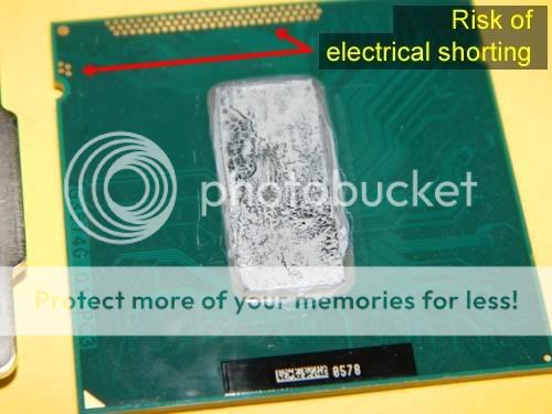
Based on what I have seen so far in terms of how far the TIM spreads when relidding the IHS, I am not at all worried about shorting. I am still a little concerned about cracking the die though.
I like your idea of covering the pads themselves as a means of mitigating the risk here, perhaps with black electrical tape?
So far I just take great care in positioning the IHS such that when it is all done being pushed around by the socket retention mechanism it (the IHS) just happens to not be on top of those landing pads. It is a bit tedious but so far I haven't had any issues making it work out.
Well I ended up de-lidding my 3770K a couple days ago. I used a single sided razor blade, and I gotta tell ya, I nearly pulled out of the task when I saw how difficult it was to get the blade in-between the IHS and pcb. I kept rocking the blade in the corners and eventually got the hang of it.
Yeah the risk of shorting on gold contacts is so small , you'd have to very badly place the IHS on the PCB.
Tips when de-lidding:
- I used a piece of 5mm-thick piece of neoprene to hold the chip during the 'operation' to not injure the SMCs (surface mounted components) under the chip.
- Find a corner that is the easiest and begin there.
- once you done the corners , you can apply more force to get the sides done, the glue is sticky so you can feel it go through, it wont go through 'fast' but still, be careful not to injure the die.
I couldn't find the Cool Laboratory LM TIM locally so just used MX4.
First some results;
4.8ghz 1.33v cinebench11.5 temps ->
Ambient ~20C
Before 52/67/50/51C
After 49/58/45/47C
Notes:
- Used a thin line of MX4 on die, also added a small thin line perpendicular to main line at ends to ensure corners of die had enough paste.
- Used Hi5 method TIM spread on IHS.
- The alignment of the IHS on the PCB can be important; try to find original placement. Also, the die is actually to the left-center of the PCB not in the center.
- Another thing to note is try not to push down on IHS too much, let the block/HSF mounting pressure minimise introduction of air bubbles in the TIM.
- This mod also evened out the temp difference of the cores. From 15C+ difference of core1 to other cores, to 9C.
- Will have to keep an eye out for any temp degradation and report back.
- After some gaming in BF3 - max temps = 57C, Starcraft 2 = 55C.
- My system is in a upright case with water cooling and I was unable to put case on its side, so installing CPU was within a very small area and upright. Anyway, this made the IHS move out of position while installing (sliding), for this reason, I think ppl might be having problems with temps after a while. If the sliding removes enough 'effective' TIM , then you may not have enough TIM and dries out quickly or air bubbles could be introduced. So in my setup, Liquid Pro would be very hard to install without gluing the IHS first, however this would introduce some lifting of the IHS, so I may use Ultra instead as it is more pasty ? Otherwise I might have to install Pro and epoxy it up before installing CPU. Temps are great but may do the LM TIM when Im holiday in a couple months.
Last edited:
WhoBeDaPlaya
Diamond Member
IC7 is a damned fine TIM. Glad I got a tube at Microcenter to try out when I bought my D0 i7 920.I have been using IC7 on my X79 build, and saw a good 5C decrease in temps compared to NT-H1 (allowed this seat for a few days too). IC7 is very thick, but doesn't need much time at all to reach peak performance.
BonzaiDuck
Lifer
Yeah . . . There's a web-site called "Overclockers.com" I think I'd been watching since 2005. Around January, 2007, Joe Citarella published an article there about diamond paste, with comparison to AS5 and about five other TIMs. And like I'd said somewhere before -- I went ahead and bought a vial of diamond powder to make my own. And -- it worked, almost as well as the stuff from Innovative Cooling. I finally bought the IC stuff; did some more tests.
I've replaced the TIM on my graphics cards with it, in addition to the CPU application. And again, as I said, the only thing better would be Indigo Xtreme or CoolLaboratory.
As much as I've heard whines over the years about the difficulty of spreading it, it just takes a bit more care, time and patience.
I suppose I've also been a little puzzled over the years, what with the available calorimeter tests, thermal resistance rating, and other information available and the basic thermal resistance properties of diamond, because -- when threads have popped up here from time to time about TIM choices -- my recommendations seemed to fall on deaf ears.
dqniel
Senior member
I couldn't believe the changes I got from switching out the stock gray stuff to IC Diamond on my Dell XPS's CPU and GPU. Load temps dropped 10-15c, and it was the difference between my fans running at their quietest levels 90% of the time rather than their mid-range (noisy) levels 90% of the time. Best $6.99 I've ever spent... multiple applications have been done since a little goes a long way.
BonzaiDuck
Lifer
I couldn't believe the changes I got from switching out the stock gray stuff to IC Diamond on my Dell XPS's CPU and GPU. Load temps dropped 10-15c, and it was the difference between my fans running at their quietest levels 90% of the time rather than their mid-range (noisy) levels 90% of the time. Best $6.99 I've ever spent... multiple applications have been done since a little goes a long way.
Well, that may speak to the low quality of OEM TIM as much as diamond thermal properties. When I ran my tests in 2007, I had a processor that was generating maybe 115W of load power, and the comparison made with AS5. I think the difference was around 5C at the same room ambient, and I'd waited for the AS5 to "cure." I got further improvements for lapping the IHS and HSF base.
In my computer tool-case, I keep many "substances" -- isopropyl, various glues, handfulls of different TIMs and applicators. For the latter, I might as well throw many of them away. But a dearth of diamond paste cannot be permitted.
TRENDING THREADS
-
 Discussion Zen 5 Speculation (EPYC Turin and Strix Point/Granite Ridge - Ryzen 9000)
- Started by DisEnchantment
- Replies: 25K
-
Discussion Intel Meteor, Arrow, Lunar & Panther Lakes + WCL Discussion Threads
- Started by Tigerick
- Replies: 25K
-
 Discussion Intel current and future Lakes & Rapids thread
- Started by TheF34RChannel
- Replies: 24K
-

-
