Creating a custom voltage on a toroidal transformer

May 11, 2008
21,668
1,295
126
As mentioned in the PM435 lcd thread, i am helping out a friend with his bench supply. I do this in parallel with the creation and design of my own bench supply.

He wants a beefier old fashion power supply. 2x0 to 30V@5A. So, 30V @ 10A.
He bought a toroidal transformer of 230V AC primary and 2 secondary coils of 35V rms @6.44A. We are going to put these secondary coils in parallel.


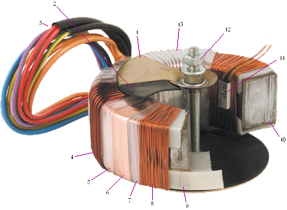
Example picture of a toroidal transformer :
tra_toroidal563e2a83a7d44f81a9a3627b63a8b06b.png


Unfortunately, the electronics can stand up about 40V absolute maximum and when the secondary rms voltage is unloaded, it will climb up to about 37V. Rectified, this would mean 52.17V (37 * 1.41). A bit to much. So i have the fun task of unwinding the transformer. I want a peak DC voltage (after rectifying) of about 37V DC so i am planning to unwind the coils to about 27V rms AC. To see if this is sufficient to get 33V@ 10A, i do have to put a load on the secondary coils and test if it will be sufficient. Otherwise, i have to solve that issue by changing the specs of the power supply. Or just use an electronic schematic that can handle the high voltage. Normally i would have already done this. But unfortunately my friend already bought the components, so this is what i have to work with for now.

I also need another auxiliary winding of about 12V @ 200mA to create a 9V stabilized supply for the PM435 lcd panel meters. Doing only this would have been easy with a toriodal transformer. Just wind a few meters of insulated copperwire and have myself an auxiliary coil. And that is what i am going to do.

As it is now, before modification, to create one secondary coil, 2 windings are put in parallel. Each winding consists of 1.35mm2 insulated copper wire. The insulation is very thin, so i have to be careful here not to damage it.

I was hoping to unwind the two wires in parallel. But unfortunately the secondary stage of the transformer consists of 4 coils layed over each other.
So, i have to unwind 3 coils entirely and one coil until i have the voltage i need. :|
The thought of having the voltage i need and delayed gratification keeps me going here.

I will post pictures later on.
 
Last edited:

SOFTengCOMPelec

Platinum Member
May 9, 2013
2,417
75
91
35V rms @6.44A.

Just a couple of quick comments.

(AC) 6.44 Amps is only 6.44/1.414 = about 4.5 Amps (DC).

BUT also remember that the voltage has significant ripple on it, depending on how big your output capacitors are.

You could easily find that, at 10 Amps (ignoring that you would probably need a higher rated current output transformer, if you/he insist on 10 Amps) the ripple, on practical/affordable/not-too-huge, input filtering capacitors, means that you need to keep the voltage over-head higher.

To compensate for voltage ripple losses, power supply drop-out time delay (so a minor blip in the mains, does NOT force the final output to drop in voltage). Also voltage drop across your voltage regulator circuitry, etc etc.

Also you may find, because of the ESR (of the filtering capacitors), may mean that combining them is NOT the most efficient design solution. But it depends ...

The above is a very quick analysis. So could be wrong.

Also, I am assuming you are talking about DC filtered, linear power supplies. If you are talking about switch mode power supplies (I assumed NOT, because you said "OLD SCHOOL"). Then IGNORE most of what I have just said.

tl;dr
Is this going to be a linear (old school) type power supply, or a modern switch mode one ?
 
Last edited:
May 11, 2008
21,668
1,295
126
It is going to be a linear one. He just needs a simple supply. And everything you have written i mentioned to him that it is going to be lower in voltage at maximum output at maximum load. But that was oke. It is just to do some quick tests, not to be used as a precision power supply.

I have created a test setup.
test_setup.jpg~original


Unwinding the transformer was easy, but time consuming. I removed the plastic covering which is similar to sticky tape but without the sticky. Then i removed three secondary coils. After that , i created the test setup. I got 3 12V/20W lamps in series to get some notion about the voltage drop with some load. I unwinded the fourth secondary coil until i got about 38V DC unloaded. That would be my target unloaded voltage. When loaded it produced 31V DC. Bit to low for my feeling but that was the limitation i already expected and mentioned. To reduce any voltage drop, i am going to add another 3 coils and they will all be 28.7 Volts AC. After that , i am going to put them in parallel with each other one by one. I am using a variac, to be able to control the transformer. I slowly increase the primary voltage and when the seconday voltage of the connected coils remain zero, or lower than expected, i got one of the coils connected with the phase reversed. If i would just connect the secondary coils and would make a mistake by reverse phase connecting them and plugging the transformer directly into the 230V AC, my 230V AC fuse would probably shutdown. It is a 500VA transformer, i think.
 
Last edited:

SOFTengCOMPelec

Platinum Member
May 9, 2013
2,417
75
91
Another thing, is that if you had an output voltage of 1 Volt. The linear regulator, would be dissipating something like 350 Watts! (35 V by 10 Amps = 350 W). (Assuming MAXIMUM output current is being used).
350 Watts can be done, but it is tricky.

One solution, is to use multiple secondaries, and a relay (or range switch, or even active switching techniques), to switch between multiple voltage steps (of the transformer). This halves (approximately), the worst case heat dissipation. (But I think that would need a different transformer, so TOO LATE!).
 
Last edited:
May 11, 2008
21,668
1,295
126
I know what you mean, since i am rewinding the coils , i could do that. Since it is a basic linear regulator without relays i would have to design that in. It is not so hard, 2 comparators with some components and 2 transistors to drive the relays. And that is needed for two 0-30V/0-5A DC circuits. I will talk to my friend about that. My friend will mostly use it for testing of motors and relays and some ready for use circuits. Thanks for the idea.
To be honest, i just want to finish it so i can continue with my own circuits.
But halving(ideally) the power dissipation would be a good idea. The casing does have huge heatsinks.
 
Last edited:
May 11, 2008
21,668
1,295
126
Just a couple of quick comments.

(AC) 6.44 Amps is only 6.44/1.414 = about 4.5 Amps (DC).

The label states that it is 35V @ 6.44A. And the rms voltage of the transformer is 35V, i measured that. So i guess they already corrected for that and the transformer can actually deliver 6.44A for each 35V coil(made up of two parallel coils). The transformer has 4 coils of 35V. And these are combined into 2 sets of coils each. That would make the transformer a 450VA model.
 
Last edited:
May 11, 2008
21,668
1,295
126
Just remembered something.
I cannot use the trick with the relay that easily because both 0-30V/5A circuits use the same input. If one is lowered and the other is higher, the voltage would not switch down. I will ask if he wants two use to bridge rectifiers and two bulk capacitors. He is paying for it.
Or i have to use an analog "or port". I have made such a circuit once with a few opamps and diodes and resistors to create an output voltage that would follow the highest of two analog input voltages.
 
Last edited:

SOFTengCOMPelec

Platinum Member
May 9, 2013
2,417
75
91
The other thing about 350 Watts dissipation, is that (in my experience). It heats up the work area too much. (Really I'm talking about 350 Watt dissipation computers).
In summer, it gets really annoying.

Most motors have huge start up currents. With some designs of PSU (especially lower current ones). The output can fall (because of the temporary excessive current), in such a way. That the motor circuitry fails to work correctly. I.e. The motor won't start up.

If you are talking about lowish current motors (< 2 Amps normal/running/rotating current), you/he should be fine.

But if the motors are close to 10 Amps, even when spun up to normal rotation speeds. Then the way the PSU handles the temporary (run up), over-current, can be important.

E.g. Some designs have current foldback, which might worsen the effect.

Without bothering to look it up. I think a motors stall current is something like 5 to 10 times the normal running current.

Sometimes the "soft" nature of the motor run up (i.e. slow start). Is liked. E.g. it saves stress on mechanical parts.

But other times, the "slow startup", is NOT desirable. E.g. Complicated Robot control, where by the motor is suppose to do stuff, within a very short time scale.

E.g. A Self balancing robot "might" fall over. If the PSU, limited the speed of changes in Motor drive current.
 
Last edited:

SOFTengCOMPelec

Platinum Member
May 9, 2013
2,417
75
91
The label states that it is 35V @ 6.44A. And the rms voltage of the transformer is 35V, i measured that. So i guess they already corrected for that and the transformer can actually deliver 6.44A for each 35V coil(made up of two parallel coils). The transformer has 4 coils of 35V. And these are combined into 2 sets of coils each. That would make the transformer a 450VA model.

Let's say, it had been rated at 10V (Vrms), at 1 Amp (AC), and was exactly 10 Watts (rating).

The DC output voltage (treating root 2 as 1.5, and the diodes voltage drop as 0. Tricks to make this example, easier).

Would be 15 Volts.

So 15 Volts could NOT be at 1 amp, because that would have needed to be a 15 Watt transformer!.

The following link, discusses DERATING transformer current ratings. When using bridge rectifier/capacitor PSU circuits. They seem to reduce the current, even MORE, than I did. As they have taken other factors into account.

http://forum.allaboutcircuits.com/threads/derating-transformers-for-rectifier-use.68839/
 
Last edited:
May 11, 2008
21,668
1,295
126
I did not forget about the peak current charging the bulk capacitor. But i was hoping that the transformer can withstand a short time delivering (less than 2 minutes) full power. To be honest, everything was already bought when i volunteered to help. I think i will add an over temperature circuit and be done with it.
 

SOFTengCOMPelec

Platinum Member
May 9, 2013
2,417
75
91
I did not forget about the peak current charging the bulk capacitor. But i was hoping that the transformer can withstand a short time delivering (less than 2 minutes) full power. To be honest, everything was already bought when i volunteered to help. I think i will add an over temperature circuit and be done with it.

Sorry, if I have wound you up.

Once you get into the finer details. Even designing a linear bench power supply, can get quite complicated.

Transformers, tend to be powerful and robust performers. But I don't in anyway advocate or recommend overloading them.

Modern (mains) transformer circuitry (in household equipment), usually has a thermal fuse inside the transformer and/or another type of over temperature cut out device fitted. From what I have seen or heard about, inside equipment.

A 30 volt, 10 Amp, all linear, bench power supply. Is NOT that easy, once you start trying to do it, in practice.
 
Last edited:
May 11, 2008
21,668
1,295
126
I am not wound up, but i did see and still do see the limitations. And worry about them. Even mentioned them. But it all does give me the "back to the drawing board" feeling. It has a current foldback current limit. I did was worried about that. That is why i use the "linear" technology bench supply (pun intended) in the other thread. So, i do not have to worry about dissipation.
And i can solve it, but it makes for so much work. :| Oh well.
 
May 11, 2008
21,668
1,295
126
Each bench supply uses a MJ4502 output transistor.
The circuit is basically an application note from National Semiconductor (Now Texas Instruments). The case is also bought and prepared, so i cannot add transistors in parallel. The supply will be mostly be doing light duty work and small dc motors of hundred watt max. I will just add that over temperature circuit. And i will think about it to create 8 coils of 14.35V AC. That way i can always add in that relay circuit with added bulk capacitor and rectifying bridge.
 
Last edited:

SOFTengCOMPelec

Platinum Member
May 9, 2013
2,417
75
91
The following (Example circuit), has got EIGHT output power transistors in parallel.
It is 20 Amp. I.e. About 4 times the rating to one-half of yours. Or double your full 10A output.

I'm use to there being multiple output transistors (in higher current linear regulators), so they can share the HUGE heat rating.

mdrc4sch.gif


Source:

One of the main drawbacks, of too few, or one, output transistor, is that they tend to fail SHORT-CIRCUIT. With potentially nasty results.
 
Last edited:
May 11, 2008
21,668
1,295
126
I know what you mean, but i am stuck to one transistor. :|
The housing is already prepared when i volunteered to help.
Everything (power) electronic is already mounted and i do not have much room to work with.
The original idea was that i would help with the pcb soldering only.
Cause it is on prototyping board.

Personally i would have made a transformer dimmer if it has to be a 50Hz transformer.
When i would make such a circuit, i would do it on my breadboard in combination with simulation on the pc and then build a prototype circuit.
I am going to eat and then prepare myself for creation of the 14.35VAC coils.
 
Last edited:

SOFTengCOMPelec

Platinum Member
May 9, 2013
2,417
75
91
I know what you mean, but i am stuck to one transistor. :|
The housing is already prepared when i volunteered to help.
Everything (power) electronic is already mounted and i do not have much room to work with.
The original idea was that i would help with the pcb soldering only.
Cause it is on prototyping board.

Personally i would have made a transformer dimmer if it has to be a 50Hz transformer.
When i would make such a circuit, i would do it on my breadboard in combination with simulation on the pc and then build a prototype circuit.
I am going to eat and then prepare myself for creation of the 14.35VAC coils.

Sorry, I did know about your limit of 1 output transistor.

I'm disappointed with whoever designed that schematic you supplied. Because they appear to be potentially over-heating the single output power transistor. Assuming Liquid Nitrogen and/or other cheats are NOT being used.

Anyway, good luck!
 
May 11, 2008
21,668
1,295
126
Sorry, I did know about your limit of 1 output transistor.

I'm disappointed with whoever designed that schematic you supplied. Because they appear to be potentially over-heating the single output power transistor. Assuming Liquid Nitrogen and/or other cheats are NOT being used.

Anyway, good luck!

Yeah, well... With my experience in electronics, i learned to never blindly trust application notes. Because application notes are examples that do not cover every situation or take into account real world use.

Common example is a highly accurate (16bit) adc with MCU fed of a 3.3V smps with very high efficiency. High efficiency smps usually go into burst mode at light loads and can have ripple on the output voltage of over 100mV. The circuit is fine as long as there is enough current drawn to prevent the smps going into burst mode. As long as it is running in the normal regulating mode, constantly switching and regulating, the ripple may be less than 10mV and can be filtered out. But the best way would be to use a linear regulator behind the smps to feed the adc.
 
May 11, 2008
21,668
1,295
126
Well, the first two coils have been wound on and are phase correct and both at 14.4V AC. Now i know in which way to wind, as long as i do it the same for all remaining 6 coils, i should be set. Sadly, i was thinking of something else during winding and lost count. Should be around 18 turns :mad:
 

SOFTengCOMPelec

Platinum Member
May 9, 2013
2,417
75
91
Linked to a switchable between 2 Toroidal secondary's (voltages), fanned heatsink to take the heat dissipation, with digital Meter readout and 10 turn voltage setting.

(Youtube) video, about making a LM317/LM350 3A 28V Hobby PSU Part1

(Youtube) What appears to be a 100 AMP! LINEAR! power supply. It makes (resistance) wires glow red hot, when connected across it. (For some reason, I suddenly want one!)

EDIT:

Also, I may be WRONG!, about the power transistor over-heating in YOUR schematic. I'm no longer sure, without spending much more time looking into it.

Because the LM317 (series), if it was on its own (which may or may NOT apply, with the external power transistor. With a quick glance, I'm NOT sure, either way), the LM317 significantly REDUCES the maximum available output current (considerably), as the voltage (drop) across it increases.

I've NOT read up on this by looking at the datasheet. But the first video I looked to above, discusses that very issue. So the switchable transformer secondaries, probably improves the maximum output current, in those circumstances.
 
Last edited:

SOFTengCOMPelec

Platinum Member
May 9, 2013
2,417
75
91
http://www.st.com/web/en/resource/technical/document/datasheet/CD00000455.pdf

Ignoring the external pass transistor, for now.

The (on its own) LM317 (above data sheet, is the ST version), only gives the FULL output current (of >=1.5 Amps), to 15 Volts (input voltage - output voltage).

It then reduces to (only) 0.4 Amps (typical), as the differential voltage reaches 40 Volts.

Because (without spending too much time reading up on the LM317), I DON'T understand what circuitry and how the adjust pin works. I'm still unsure, how it will behave, with the external transistor.

I also don't know where, exactly, you got that schematic from. I.e. a link or other reference, would be needed.
 

SOFTengCOMPelec

Platinum Member
May 9, 2013
2,417
75
91
The schematic is in French, but what it says is Linear databook 1. National semiconductor 1987, p 1-56.

But you can also find it here in this English version at page 115 (10-13) :
It is a digitized version of the application book.

https://archive.org/stream/NationalSemiconductorVoltageRegulatorHandbook1980#page/n113/mode/2up

EDIT:

I should note that R8 is 4.7kOhm in the schematic i received.

Thanks.
Early indications (so I can make excuses if I am WRONG) are that it will happily pass the extra current (heading towards your 5 amps), without involving the LM317's in-built current limits.

Somehow (it was probably TOO SMALL to see easily), I missed the external 0.2 Ohm resistor. So I could NOT see how the current limit was being sorted out.

How big/powerful is your case's (TO3), heatsinking ?

Is it just thin drilled sheet aluminium, or has it got a real, thick heatsinking section(s) ?

Do you know its Degrees per watt rating ?
(if not, don't worry, I'm just being curious).

Since it is a hobby/quick PSU you are building (if I understand correctly), I guess you are not too bothered.