• We’re currently investigating an issue related to the forum theme and styling that is impacting page layout and visual formatting. The problem has been identified, and we are actively working on a resolution. There is no impact to user data or functionality, this is strictly a front-end display issue. We’ll post an update once the fix has been deployed. Thanks for your patience while we get this sorted.

Question Seagate Internal Desktop IDE HDD PCB Repair

gaurav279

Junior Member
Hi All...
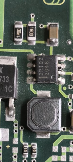
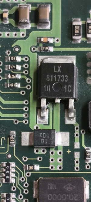
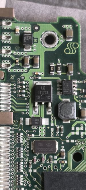
I have an old 40GB Seagate Internal Desktop IDE HDD. The PCB of this HDD has got some components burnt as a reverse polarity IDE connector was accidently connected to it - ie.5V connector pin was connected to 12V socket and 12V pin was connected to 5V socket. The drive was immediately removed.

Currently when I connect the drive to the IDE power connector (with the corect orientation), I noticed that the drives motor rotates but the drive is not reading. I tried it on a Desktop Mother board as well as an external IDE-USB reader on laptop.

Iam posting some photos of the drive. It would be kind and great if some experts on the subject could guide me as to how can I repair this drive and recover the data on the same.

MAny Thanks & regards

Gaurav U Sharma
INDIA
IMG_20260111_130456.jpgIMG_20260111_130427.jpgIMG_20260111_130440.jpgIMG_20260111_130456.jpgIMG_20260111_130427.jpgIMG_20260111_130427.jpgIMG_20260111_130611.jpgIMG_20260111_130456.jpgIMG_20260111_130427.jpg
 
Your best bet is to send the drive to a data recovery business.
@bba-tcg
Thanks for writing in. My primary objective of posting the issue in this esteemed forum is to get guidance on how to repair the PCB.

Data recovery is the last option that Iam looking for which you can also understand is a very expensive affair
 
@bba-tcg
Thanks for writing in. My primary objective of posting the issue in this esteemed forum is to get guidance on how to repair the PCB.

Data recovery is the last option that Iam looking for which you can also understand is a very expensive affair
Sure. I'm just saying that I personally believe you're just delaying the inevitable if you want your data.
 
I haven't tried that with a hard drive, but my thoughts on how I would attempt it are:

You would need to determine which components those are and then replace them. If you can find high resolution scans or schematics that will help.

Barring that, you can buy the same model drive, and either use it as a guide for parts, or a source for parts, OR swap the board over. IIRC this is the approach that seems to have the best chance of success for home user restoration efforts.
 
Swapping PCB sounds like a good choice if you can find a used one. But I wonder if a different PCB will have different bad sectors mapped, possibly not reading drive sectors with good data.

Based on ebay pics of Seagate 40GB IDE/ATA PCB's, the square device appears to be a 5v-to-3.3v regulator...... STMicro LD33c or equal. It likely failed/shorted when 12v was applied to the 5v pin. You can verify with a DMM on diode scale by testing between any two pins. DMM will beep if a short exists. Damage to downstream components remains a possibility, but if regulator failed quick, you could be OK. This is DIYable. Regulators are on ebay. Any electronic repair shop should be able to repair.

Looks like I can't post a ebay link to PCB photo.

LD33c is a part of 1117 series regulator
Here's what Google AI says.....

1768691708303.png


Good luck


1768691708303.png
 
I haven't tried that with a hard drive, but my thoughts on how I would attempt it are:

You would need to determine which components those are and then replace them. If you can find high resolution scans or schematics that will help.

Barring that, you can buy the same model drive, and either use it as a guide for parts, or a source for parts, OR swap the board over. IIRC this is the approach that seems to have the best chance of success for home user restoration efforts.
Hi...
Thanks for writing in. Finding a replacement board of this old IDE HDD is virtually not possible in the city I live in India.

If you can pls suggest where I can find online some high resolution scans or schematics for this particular drive ...
 
Swapping PCB sounds like a good choice if you can find a used one. But I wonder if a different PCB will have different bad sectors mapped, possibly not reading drive sectors with good data.

Based on ebay pics of Seagate 40GB IDE/ATA PCB's, the square device appears to be a 5v-to-3.3v regulator...... STMicro LD33c or equal. It likely failed/shorted when 12v was applied to the 5v pin. You can verify with a DMM on diode scale by testing between any two pins. DMM will beep if a short exists. Damage to downstream components remains a possibility, but if regulator failed quick, you could be OK. This is DIYable. Regulators are on ebay. Any electronic repair shop should be able to repair.

Looks like I can't post a ebay link to PCB photo.

LD33c is a part of 1117 series regulator
Here's what Google AI says.....

View attachment 136852


Good luck


View attachment 136852
Dear Agent13,
Thank You Very much for your kind reply. I cleaned the PCB with IPA solution and tested the square shaped component, which is primarily on the top circuit l, just below of the IDE supply terminals. The same is marked with a value which reads LX-811733/10 1C. I checked the same with my DMM. When I tested this part, the meter doesn't beep but it's showing some values on both the legs (barring the middle one ie. ground). I also checked almost all the SMD components in this area but all of them show some or the other values when I checked using my DMM in the continuity mode.

Any thoughts on this from your side please ....


Many Thanks

Gaurav U Sharma
India
 

Attachments

  • IMG_20260122_163829.jpg
    IMG_20260122_163829.jpg
    323.1 KB · Views: 7
  • IMG_20260122_163811.jpg
    IMG_20260122_163811.jpg
    395.9 KB · Views: 7
  • IMG_20260122_163904.jpg
    IMG_20260122_163904.jpg
    424 KB · Views: 7
Wow, that cleaned up much better than I expected.
Shorting isn't the only failure mode.
The middle (short) leg is tied to the tab above the "LX", so testing those (2) legs will always show short.
Use the ohms position on DMM and
Test 1-2 fwd and reverse leads, record resistance, ohms
Test 1-3 fwd and reverse leads, record resistance, ohms
Test 2-3 fwd and reverse leads, record resistance, ohms
If fwd and reverse resistance is the same, regulator has likely failed.


Since It looks like the debris originated from the voltage regulator, I would replace it first.

I can't post a .pdf or a link to the datasheet. Google LX811733 and you will find an Alldata link.

EDIT:
The 8 leg device is a DC-DC converter.
Google FDFS2P102 and you can find the datasheet.


1769267669965.png
 
Last edited:
Wow, that cleaned up much better than I expected.
Shorting isn't the only failure mode.
The middle (short) leg is tied to the tab above the "LX", so testing those (2) legs will always show short.
Use the ohms position on DMM and
Test 1-2 fwd and reverse leads, record resistance, ohms
Test 1-3 fwd and reverse leads, record resistance, ohms
Test 2-3 fwd and reverse leads, record resistance, ohms
If fwd and reverse resistance is the same, regulator has likely failed.


Since It looks like the debris originated from the voltage regulator, I would replace it first.

I can't post a .pdf or a link to the datasheet. Google LX811733 and you will find an Alldata link.

EDIT:
The 8 leg device is a DC-DC converter.
Google FDFS2P102 and you can find the datasheet.


View attachment 137201

Dear Agent13,
Thanks again for your kind reply and enthusiasm to resolve my HDD issue.

I tested the resistance (using my DMM) across the mentioned points and below are the results denominating the PIN Nos. measured in Ohms on the 2000 Ohms scale -

Pins 1 & 2 = 366E (Forward)
Pins 2 & 1 = 697E (Reverse)

Pins 1 & 3 = 498E (Forward)
Pins 3 & 1 = 823E (Reverse)

Pins 2 & 3 = 566E (Forward)
Pins 3 & 2 = 892E (Reverse)

Since the forward and reverse resistances are not the same, the Voltage Regulator LX811733 has not failed per say.


I tried connecting the 40GB HDD to my laptop via IDE Data cable and external IDE power supply. The drive is spinning very well and sound of the spin is distinct and clear.

If you can please guide me further on the way ahead...


Many Thanks
Gaurav U Sharma
Mumbai,
INDIA
 
Last edited:
Based on the residue, I believe the regulator has been damaged.
With drive connected to PC or laptop can you confirm there is 5v on pin 3 and 3.3 v on pin 2 when measured to pin 1 (gnd)?

1769470883363.png
This might be difficult,
 
Based on the residue, I believe the regulator has been damaged.
With drive connected to PC or laptop can you confirm there is 5v on pin 3 and 3.3 v on pin 2 when measured to pin 1 (gnd)?

View attachment 137395
This might be difficult,
Hello
If the regulator is damaged how come it's showing resistance values when measured across.

In the previous post you mentioned Pin 2 is the ground ...now you have mentioned pin 1 as ground ?

Can the voltage be checked in a running drive ???


Many thanks

Gaurav U Sharma
INDIA
 
........If the regulator is damaged how come it's showing resistance values when measured across......

.......In the previous post you mentioned Pin 2 is the ground ...now you have mentioned pin 1 as ground ?.....

......Can the voltage be checked in a running drive ???..........
The regulator is an integrated circuit with multiple components. Internal components can fail preventing operation without creating a short. You cannot detect a regulator open circuit when testing in-circuit due to the presence of external components which have resistance and affect an in-circuit measurement.

We are moving down a testing path.....no shorts, fwd/rev resistances are different and now we need to test output voltage.

You can check regulator voltage of a running drive if you can access the regulator. Be careful you don't accidentally short two adjacent components while measuring.
Does the regulator get hot when drive is running?

I don't see where I said pin 2 is the ground. The datasheets are clear. Both LD33C and the LX811733 have the same pin-out.
Dear Agent13...
Thanks again for your kind support. I searched online and Iam getting

SL1117-3.3D-Slkor-TO-252 Voltage Regulators – Linear, Low Drop Out (LDO) Regulators ROH.​


Will this Voltage regulator work in place of this LX811733 Voltage regulator which we see as the most probable part to be damaged in the process.

Also kindly advise if I remove this LX811733 and then test it ....how should I do so and for what values should I check.

Other defective component I see is the 2P102 - 8 pin IC. Can you pls suggest how to test this IC for whether it's working or not ....

Is there any alternative available for this 2P102 8 pin SMD IC


Many thanks & warm regards...

Gaurav
India
 
The SL1117-3.3D is functionally the same as the LX811733, but it is in a T0-252 case and likely will not fit on your circuit board. CORRECTION: TO-252 is the same as DPAK case so this regulator should fit without ant issues. The regulator must be soldered to the PC board for cooling. You need a device with a D-PAK case.

If you remove the LX811733 you can test it on the bench with a 5vdc power supply. There are youtube video's showing how to do this.

I don't know what the FDFS2P102 does in this circuit. It may stop-start the drive motor or regulate the drive motor voltage. It is a Schottky diode (Pins 1&8) and a MOSFET (Pins 3,4&6) in a single device. These can be tested with a DMM. You will have to search for the pdf of the FDFS2P102 as the forum doesn't allow pdf attachments.

Google:
How do i test a Schottky diode with multimeter
How do I test a MOSFET with a multimeter

BadcapsDOTnet is a good resource for troubleshooting defective electronics.
 
Last edited:
The SL1117-3.3D is functionally the same as the LX811733, but it is in a T0-252 case and likely will not fit on your circuit board. The regulator must be soldered to the PC board for cooling. You need a device with a D-PAK case.

If you remove the LX811733 you can test it on the bench with a 5vdc power supply. There are youtube video's showing how to do this.

I don't know what the FDFS2P102 does in this circuit. It may stop-start the drive motor or regulate the drive motor voltage. It is a Schottky diode (Pins 1&8) and a MOSFET (Pins 3,4&6) in a single device. These can be tested with a DMM. You will have to search for the pdf of the FDFS2P102 as the forum doesn't allow pdf attachments.

Google:
How do i test a Schottky diode with multimeter
How do I test a MOSFET with a multimeter

BadcapsDOTnet is a good resource for troubleshooting defective electronics.
Thanks for your reply Indeed. Shall do this and update you in this space
 
@gaurav279, your components were identified for you two weeks ago in your identical thread at Tom's Hardware:

https://forums.tomshardware.com/thr...de-internal-desktop-hdd.3891752/post-23584653

https://forums.tomshardware.com/thr...de-internal-desktop-hdd.3891752/post-23584690

LX8117-33 is a 3.3V regulator. Its output voltage should be +3.3V.

The FETKY is part of an inverting buck converter which produces an output voltage of -5V. That's the negative supply for the preamp on the headstack.

As I told you in that thread, my approach would be to test the resistance of the preamp, but I would need to see the other side of the PCB to identify the test points. If the preamp is shorted, then it's game over for you.
 
Last edited:
Back
Top