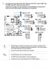
This mobo is one I've not seen before, and its manual does NOT include mention of some configuration features common on other mobos. Those include the ability to adjust the minimum speed of a fan that will trigger a fan failure warning and action, and a means to set up a custom "fan curve" - that is, to set several values of fan speed for measured temperatures. I also am accustomed to seeing at least two different temperature sensors on a mobo. One is the sensor already built into every CPU chip; since your system has two such chips, I would have expected to see two such CPU temp sensors available for use. These are used specifically to guide the cooler system (fan and heatsinlk, or other) for each respective CPU chip. Then I normally see at least one general motherboard temp sensor commonly used to guide the case ventilation fans that usually are connected to CHA_FAN or SYS_FAN headers.
Your mobo has eight fan headers, and all of them are specified as being ONLY used for PWM Mode control. Thus they are NOT well suited to use with older 3-pin fans. Of these, six are labelled with numbers 1 thought 6, and the other two are labelled A and B. I might GUESS that the A and B headers are for coolers on the two CPU chips (not clear which is which) and the other six for case ventilation fans. HOWEVER, that is just my GUESS, and there is no statement in the manual about what those eight headers are supposed to serve.
There are two major types of device used to connect several fans to a single header. The simpler is a SPLITTER which simply connects all its fans in parallel to the fan header power lines, and thus all fan power must come from that host header. The header itself normally is limited to a max of 1.0 A current to all its fans, so that limits how many fans one can use with a Splitter. (Typical fan currents max out about 0.10 to 0.25 A each.) A fan HUB, on the other hand, does it differently. It MUST have a PWM signal from the host header (via Pin #4) and must also have a connection to a Molex or SATA power output connector from the PSU. That power connection is the source of power for all the fans, thus NOT using any power from the host header and avoiding its limit. The HUB distributes power from the PSU to all its fans, and the PWM control signal from the mobo header to those fans. Thus it depends on having ONLY the newer 4-pin PWM fans attached, because only those fans can use the PWM signal to modify the fixed +12 VDC power supply they receive and control their own speed.(See the end.)
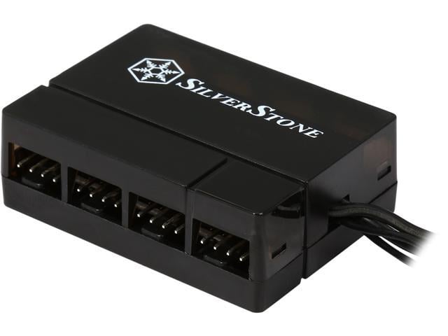
Since your mobo has ONLY PWM Mode fan headers, ALL of the fans in your system really should be of the new 4-pin type. (Any 3-pin fan connected to such a header will always run full speed). So if you do have only 4-pin fans, I suggest you do NOT want that Phanteks PWM Hub. It is one of a VERY few Hubs that operate differently. It takes the PWM signal from the mobo header and creates in its own circuits a set of six older-style 3-pin fan headers that use the older Voltage Control Mode. (In that Mode, fan speed is controlled by varying the voltage supplied on Pin #2.) This "conversion" feature is VERY useful if you have PWM fan headers but 3-pin fans. However, I hope you do NOT have that mis-match to deal with. So I suggest your better alternative is a different 4-pin fan Hub, and here are just a couple of examples. This one from Silverstone had 8 output ports
Buy SilverStone PWM Fan Hub System Cables, Black (CPF04) with fast shipping and top-rated customer service. Once you know, you Newegg!

www.newegg.com
This Deepcool FH-10 model has 10 outputs
Do NOT get the Deepcool FH-04 device - it is just a Splitter.
I assume your plan is to connect several CASE vent fans to a single mobo header, and the actual CPU coolers are being done separately, which is best. Many of these Hubs tell you to connect its fan header cable to the mobo CPU_FAN header, but you do NOT need to do that. That advice is solely for use with some older mobos that used the required PWM Mode of control only on the CPU_FAN header, and you do not have that limit. But do note that all of them have ONE of the output ports identified (often with a "CPU" label) as the only port that will send its fan's speed back to the mobo.
You are hoping to avoid sending a fan speed signal back to the host mobo header to stop it from detecting a slow fan and trying to speed it up continually. I am hoping NOT to do that, and here's why. A mobo fan header has three functions. It provides power to the fan. It provides a means to control the speed of the fan. And lastly, it monitors the fan's speed signal for FAILURE. Yes, the speed CONTROL does not use the speed signal, but FAILURE detection does.) Your mobo's fan headers are detecting fan speed less than its lower limit and trying to correct that with some success. If they receive NO speed signal, they will likely become more aggressive in their actions with prominent warning messages and perhaps by shutting down your system for lack of cooling (even though the TEMPERATURES may be OK). Now, when you use a Hub and it sends back only one fan's speed signal to monitor, the mobo cannot check all the other fans for failure, but that's just the way these work. So it really is best to ensure that the Hub DOES send back the speed of one fan by plugging one into the special output port. But that still leaves you open to your current problem.
I suggest a few ways to fix this.
1. Look though the BIOS Setup screens to see what fan header configuration options you have, in case there are some that the manual does not tell you about. Look for a way to set the minimum acceptable speed (the "fan failure" speed limit) for the fan. Or, see if there is a place to specify that the system will never try to run the fan speed slower than some value.
2. If those are not found in BIOS Setup screens, look in the Superdoc 5 utility and see if such control options are offered there.
3. Last option is to try to "fool" the system. One common cause of this problem for others has been using large 140 mm fans - they typically offer much higher air flow rates but at lower rotational speeds, and this can trigger the low-speed problem you have experienced. On the other hand, most smaller fans run at faster speeds when given the SAME control signals as large fans. You are considering 70mm fans (although that is pretty small, but I assume you have reasons) and a 120 mm fan. If the new fans have a maximum speed spec higher than your current fans, then ensure that the FASTER fan design is the one you plug into the only Hub output that will send back a speed signal. That may result in having faster speed signals sent back, and stopping your problem.
There's a bit of confusion above about what fan signals are and do, so let me explain FYI. This is limited to the newer 4-pin PWM fan system - I'll ignore the older 3-pin fans for this. The signals on the mobo fan header are:
Pin #1: Ground
Pin #2: +12 VDC constant power supply
Pin #3: Speed signal - 2 pulses per revolution generated in the motor and sent back to the header for counting
Pin #4: PWM signal - 25KHz pulses used by a chip in the motor housing to modify current flow from the +12 VDC source through the windings, thus changing speed.
The control system really is a TEMPERATURE control system. That is, in each case the system looks at an actual temperature measured by a sensor and compares that to a target, then changes fan speed if the real temperature is off target. It will increase or decrease fan power signals to whatever it takes to get the right temperature, but it actually does not worry about the real SPEED of the fan. The speed signal is used almost exclusively to verify that the fan is working and not stalled.