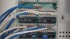
Ok, so you used the toner function to trace out the patch panel drops to the rooms. That's a good start!
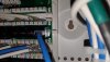
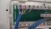
Move on to the 3 drop test pics. Are any of those 3 drops working? I kinda assume not based on the patch panel picture with the layout notes on it.
Here's the manual:
https://www.elegiants.com/downfile.html?path=/elegiants/20171110/5a06681a4934c-ELEGIANT Bside FWT1 Product Manual.pdf
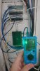
Below is the section to use, and it appears that you're doing it correctly. You have the receiver plugged into the corresponding drop at the other end of the run, using another patch cable, correct? It kinda looks like the lit up wire indicates it's "open" aka not punched down all the way.
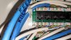
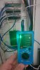
For example, in picture 111555.jpg, the number "2" is lit up. Since it's laid out pin's 1 thru 8, I would automatically assume it's pin 2 that is open. In 568A, that would be the solid green cable..
BUT, the guide specifically says "open circuit: on the receiver, the corresponding line pair indicator will not turn on". We know there's 4 pairs, and only the number 2 is lit. Based on the guide, this may indicate pairs 1, 3, and 4 are OPEN.
As the tool is not from a known brand to me, I would suggest this:
To confirm you know how to use it properly (and for a sanity check, we all have to do it sometimes lol), I would just test a patch cable or 2 with the emitter/receiver without sending it thru the infrastructure. make sure you know what it should look like when it works 100% end to end.
After that, try again, if you get the same results, inspect a drop and ensure all the punch downs look ok. Once you're familiar with the tool, I would focus on one drop at a time, sanity check against known working cabling as needed.

edit: video of basic function