Dell XPS 710 BTX to ATX Conversion

John Tauwhare

Member
Dec 26, 2012
137
5
81
Hi

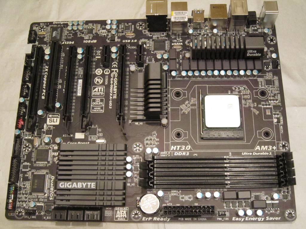
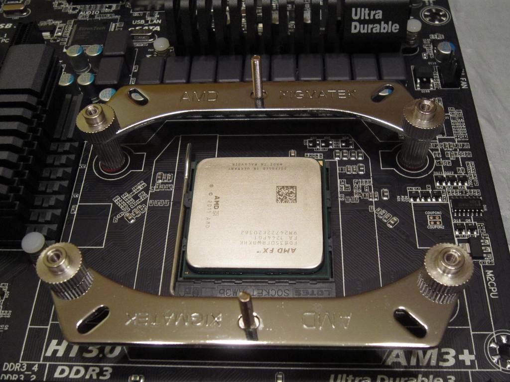
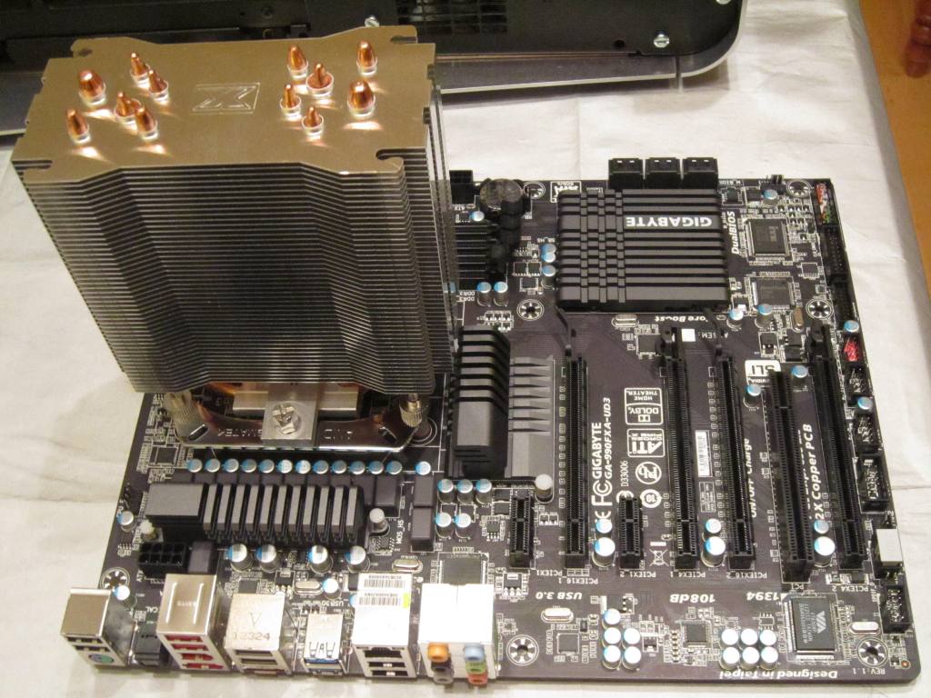
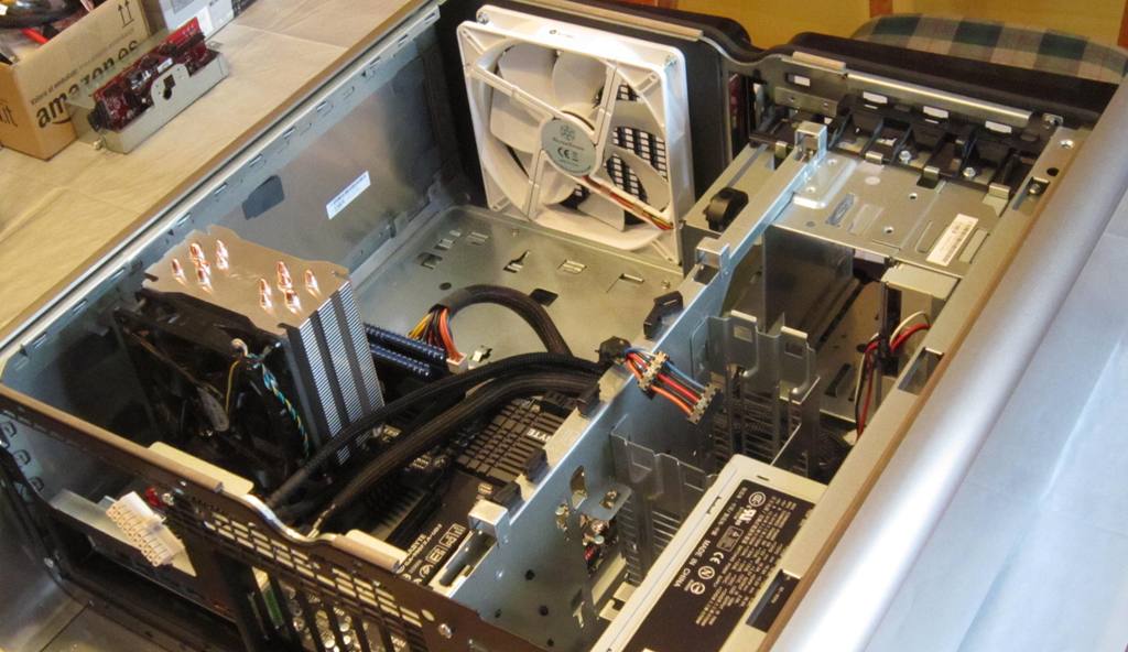
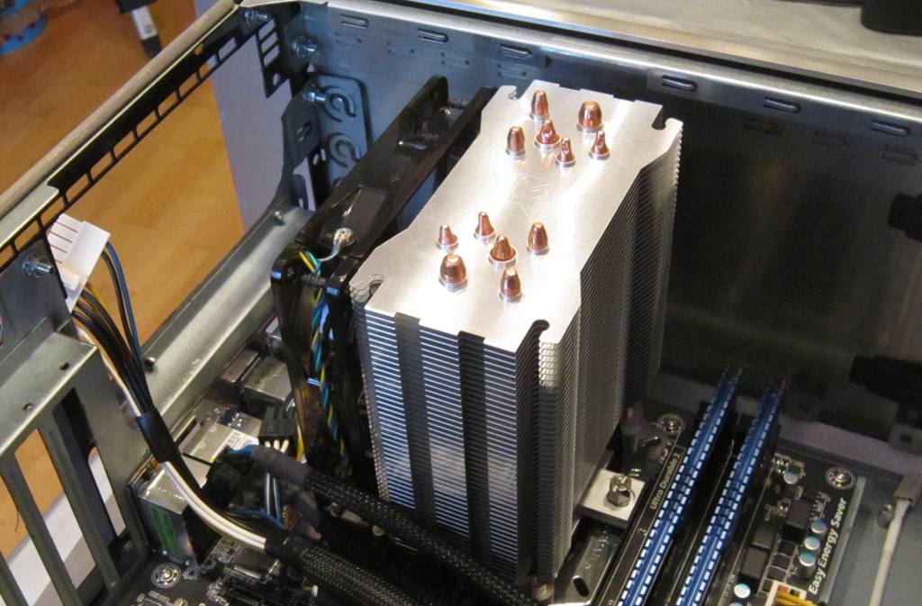
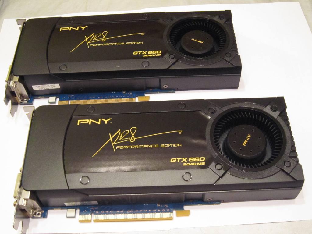
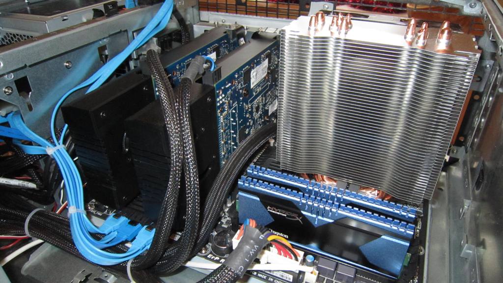
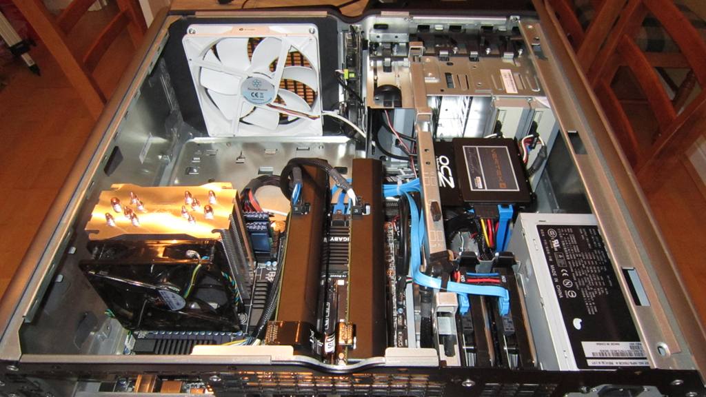
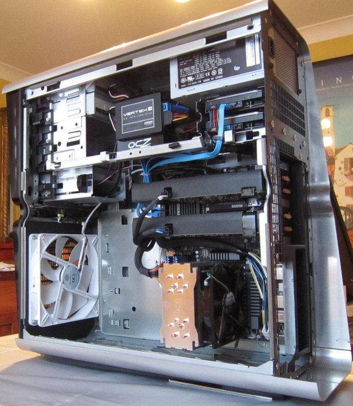
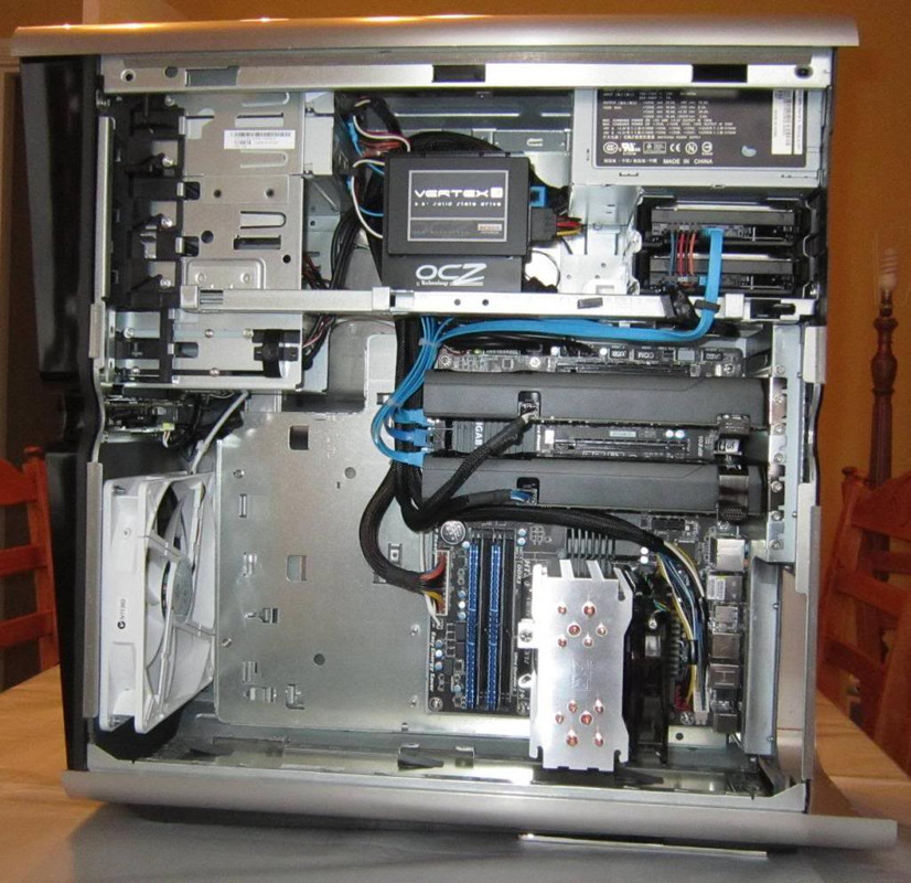
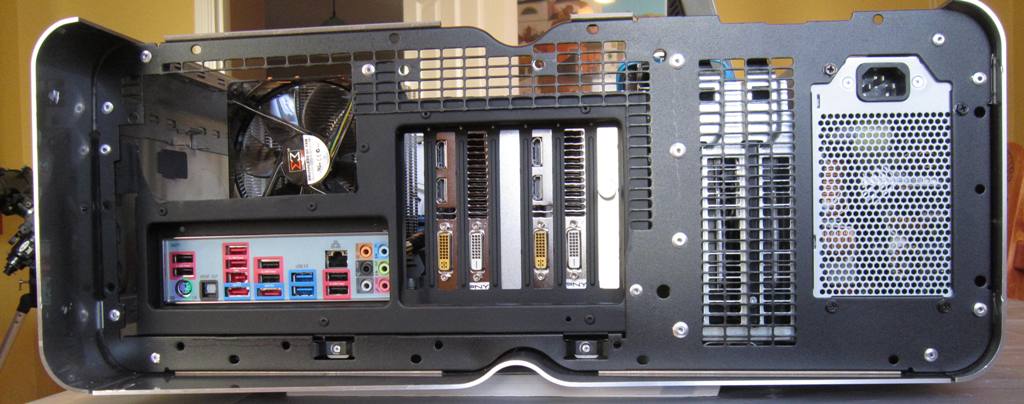
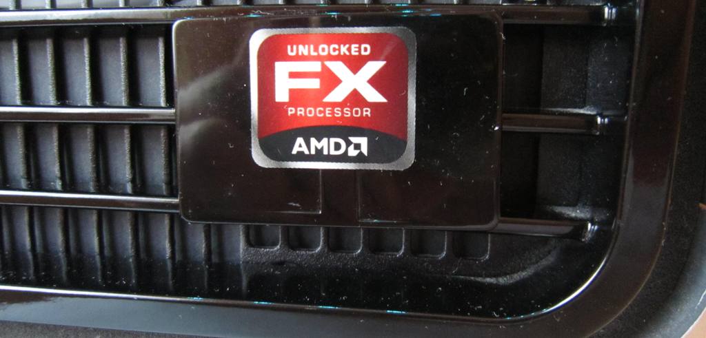
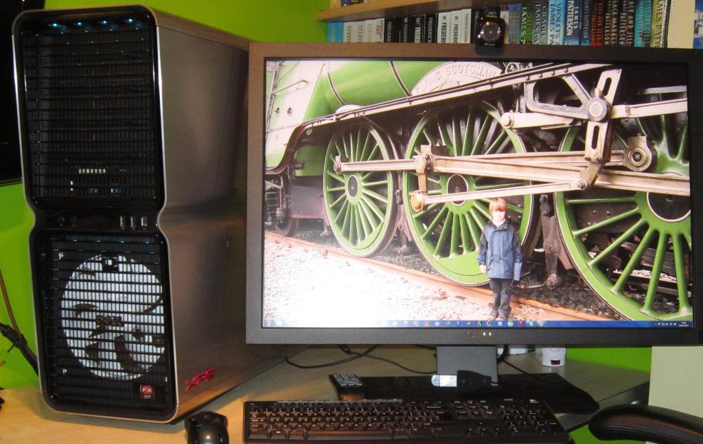
I bought a Dell XPS 710 with a QX6700 CPU back in May 2007, and it was my main computer at home for the next 5 years. Until one day in October 2012, when it refused to switch on. I thought (and hoped) the problem might be in the PSU and bought another on eBay for £35. But it still wouldn't start and I had to accept the motherboard, known to be a weakness on these machines, had expired. Unwilling to invest further in failure by buying a replacement BTX mobo I bought a Coolermaster HAF922 case, ASUS P5K mobo, Zalman CNPS9900 cooler and OCZ 750W PSU. Into the new case I transferred the QX6700, DDR2 RAM, HDDs, DVDs, and soon I was up and running again.

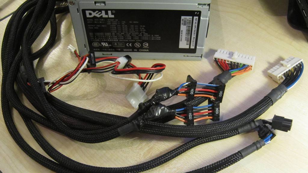
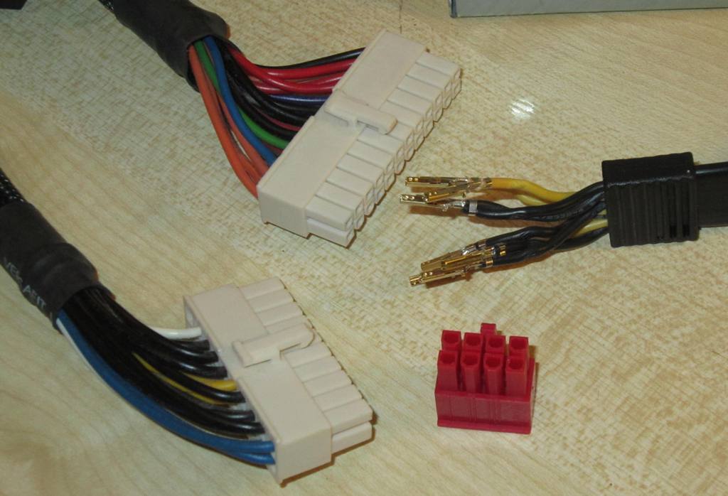
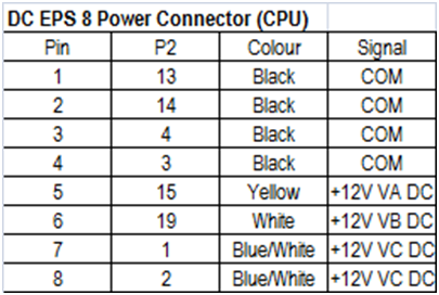
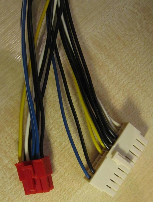
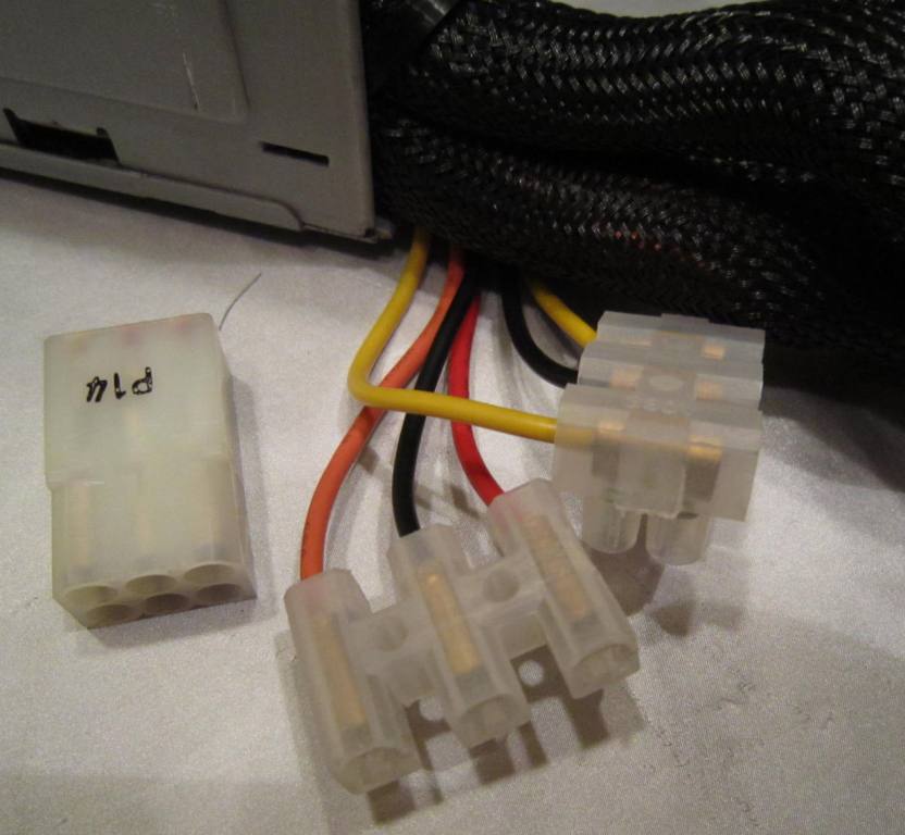
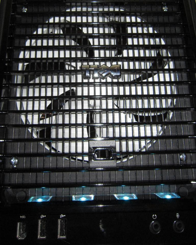
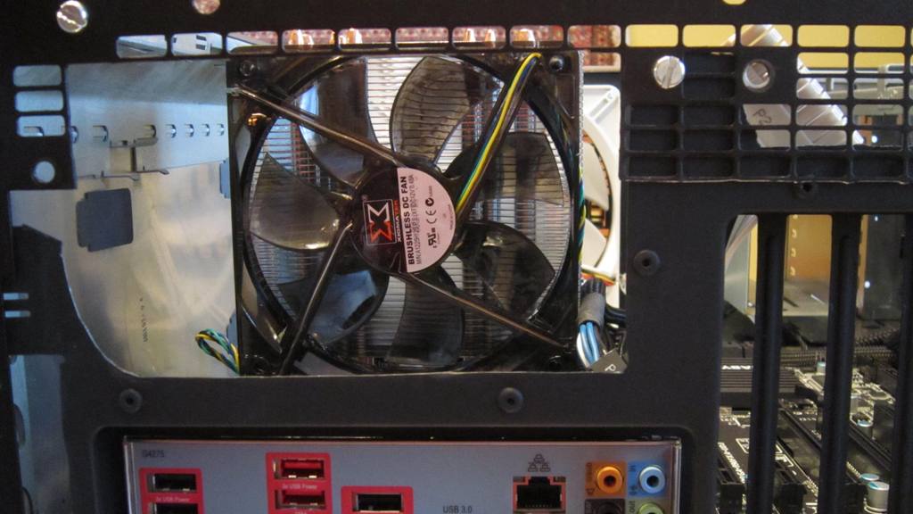
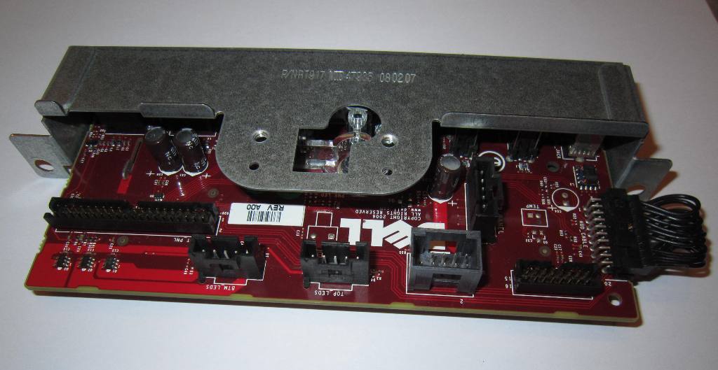
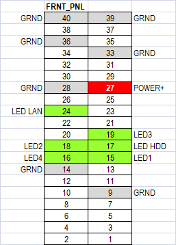
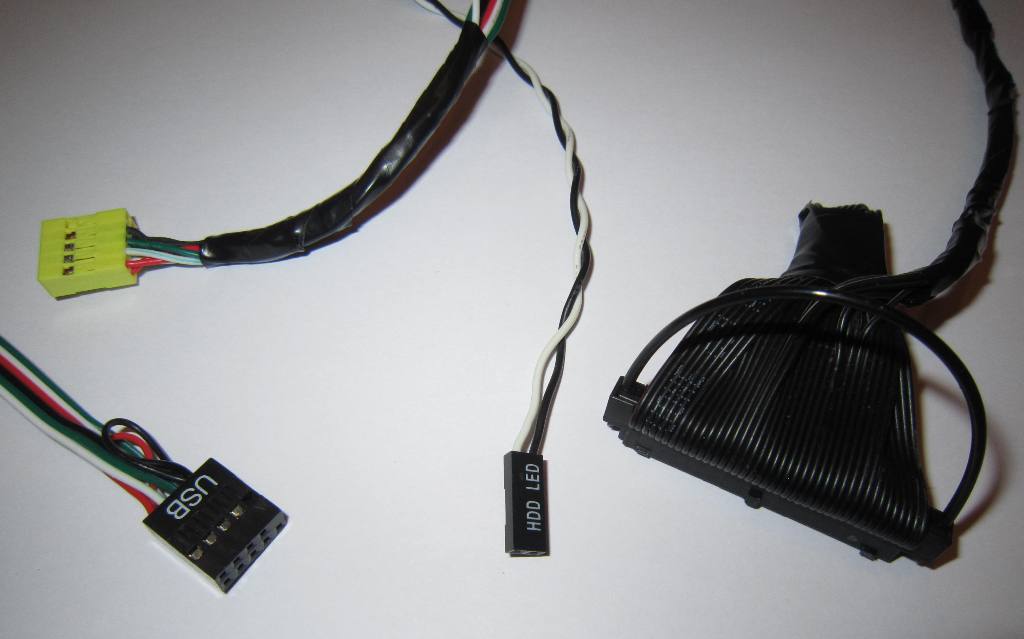
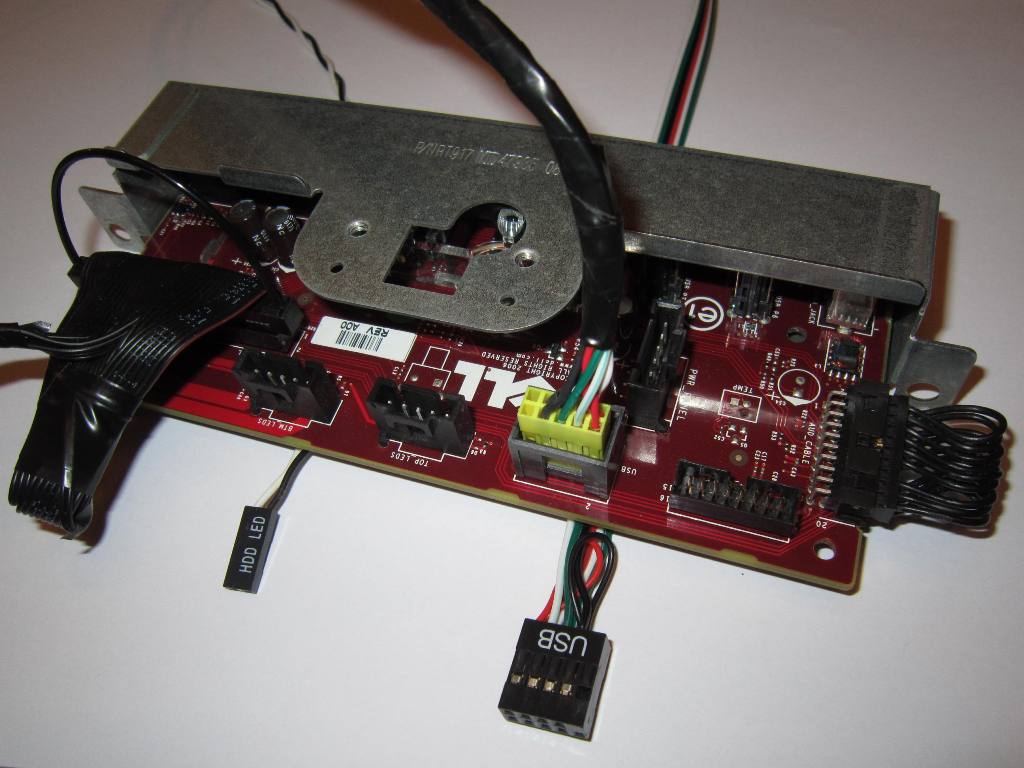
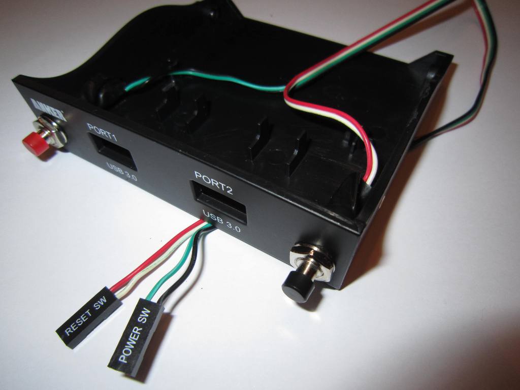
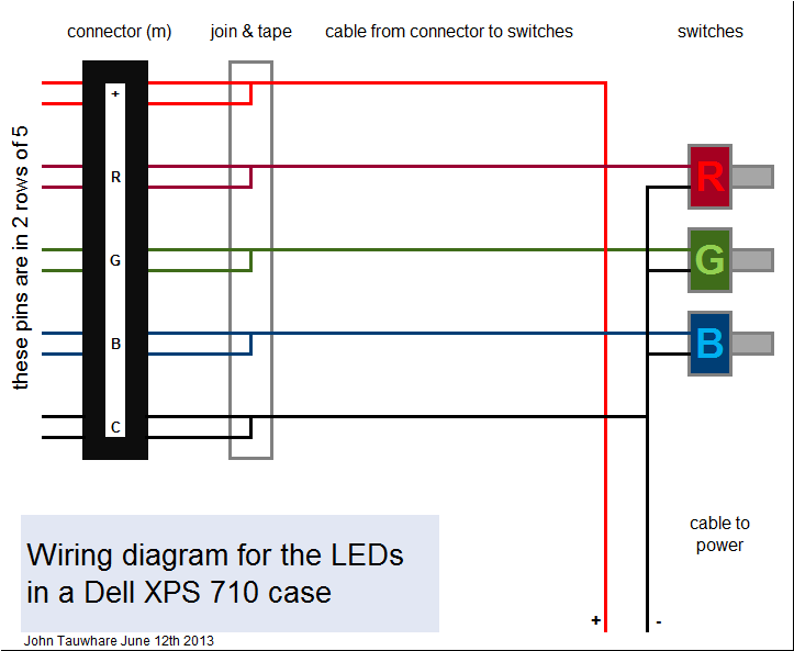
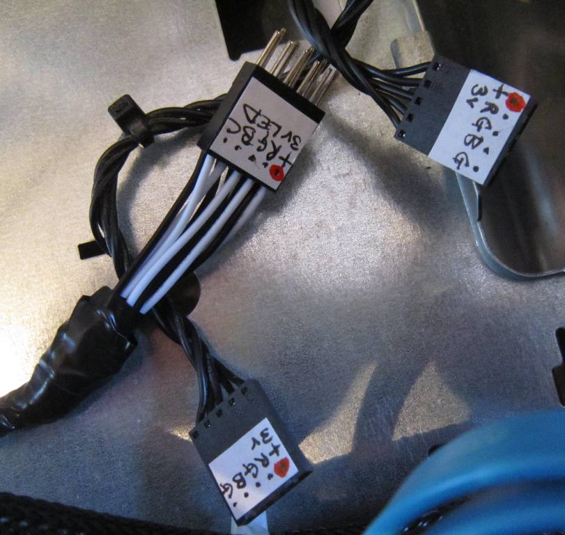
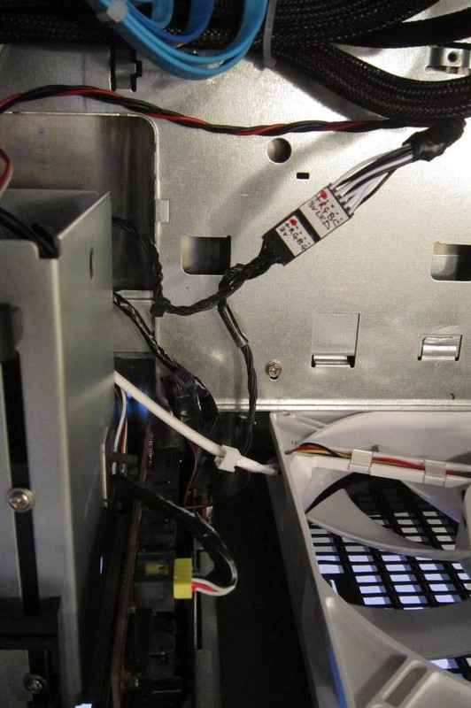
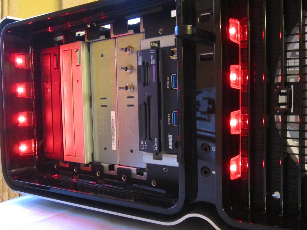
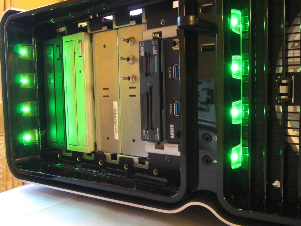
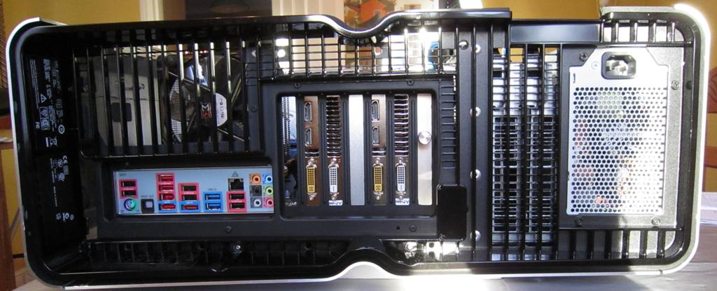
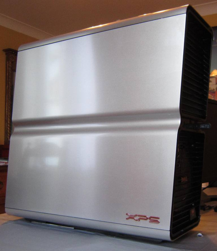
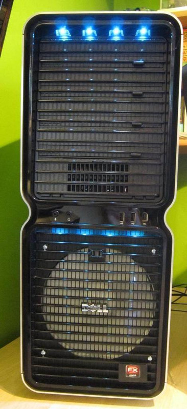
But I missed that gorgeous Dell XPS case and wanted to use it to build a new rig. However, there are issues: the main one being that its BTX motherboard has the slots on the left and the ports on the right, but BTX is old-tech (socket 775 stuff) and upgrading to an ATX board means having to accommodate the case to accept ports on the left and slots on the right. There are other issues: with the proprietary Dell PSU and with the front panel and the LEDs.

A bit of time on Google showed that a number of people had converted the case to accept an ATX motherboard. It didn't look easy, requiring good skills at metalwork and electrics. And some people went as far as welding and painting. Nevertheless, aiming more at crude-but-functional than perfection, with my limited skills and toolset, I decided to have a go.

I took a few pictures along the way, and having now nearly succeeded, I thought I'd share the experience..
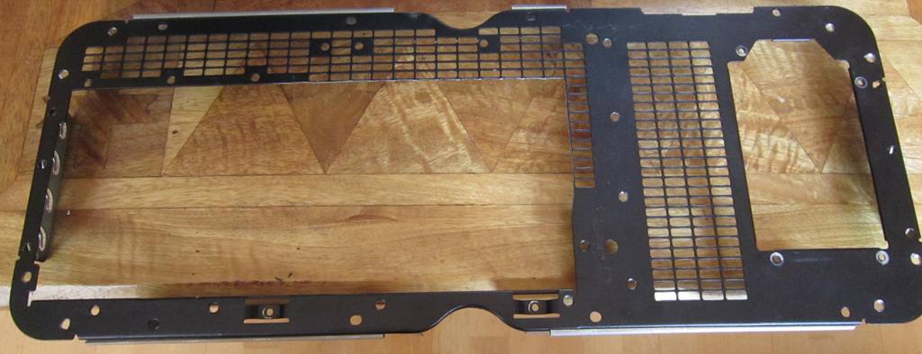
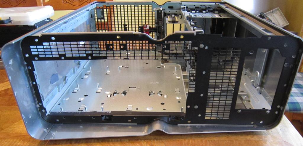
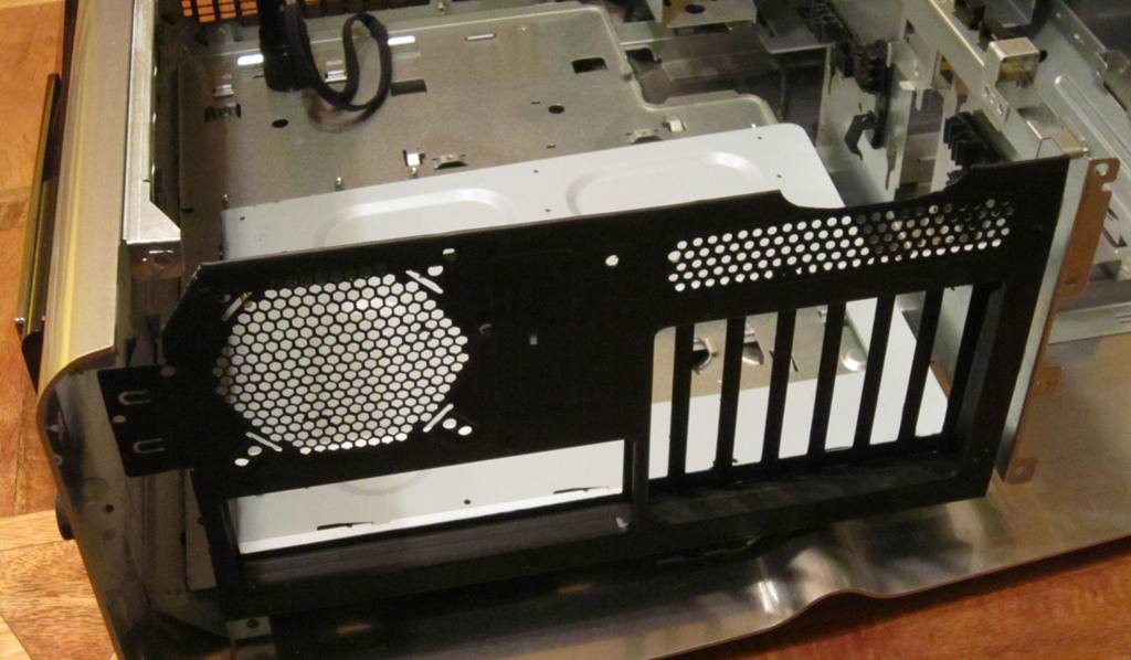
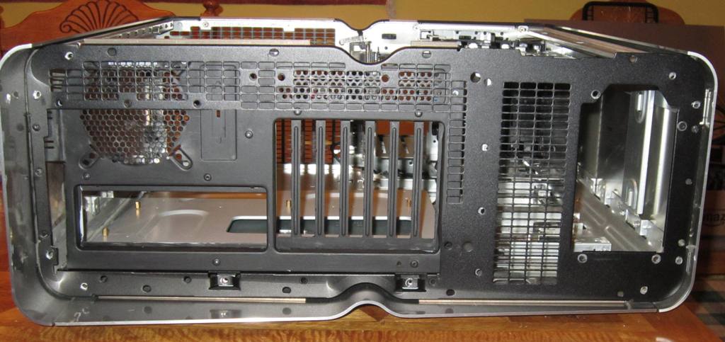
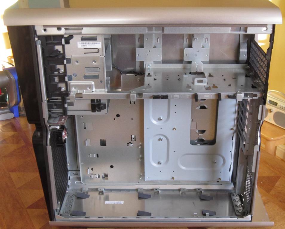
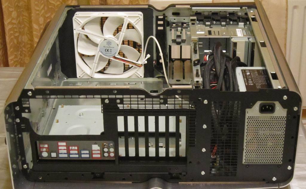
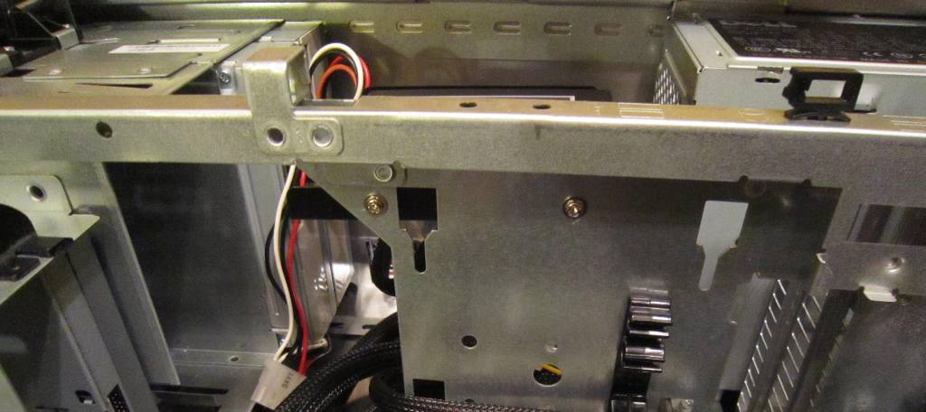
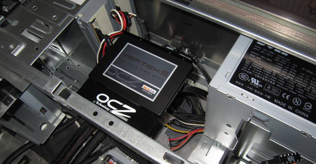
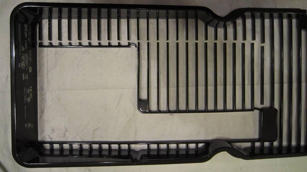
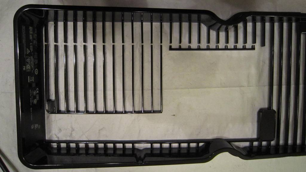
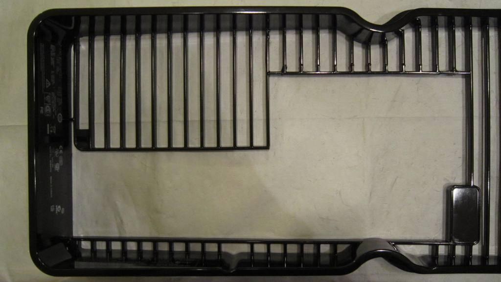
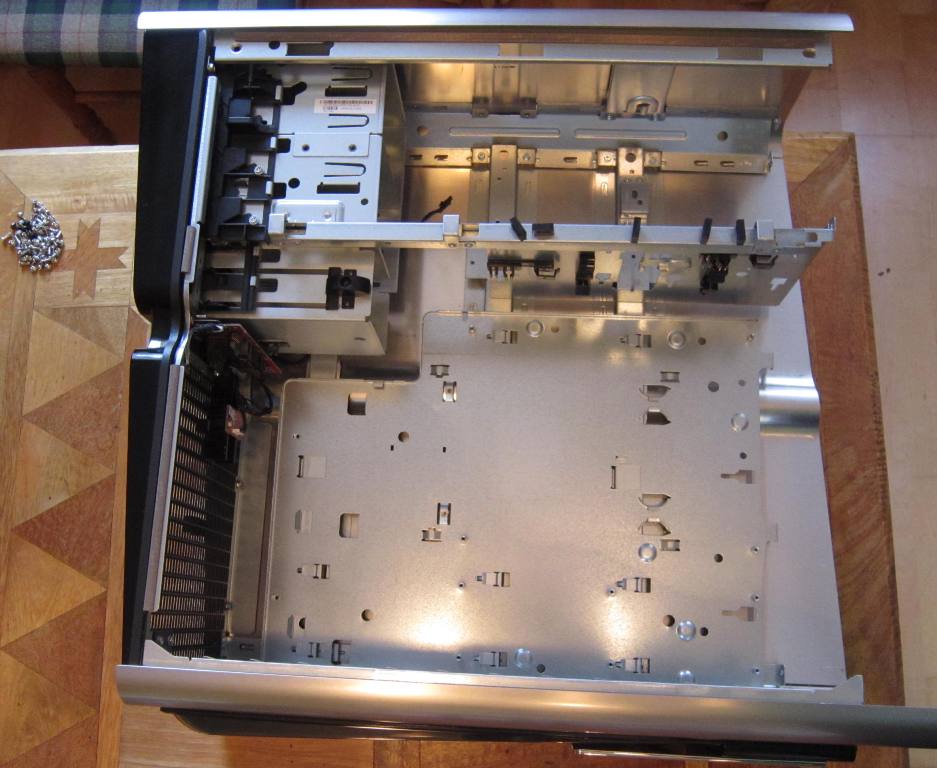
1. GUT THE CASE

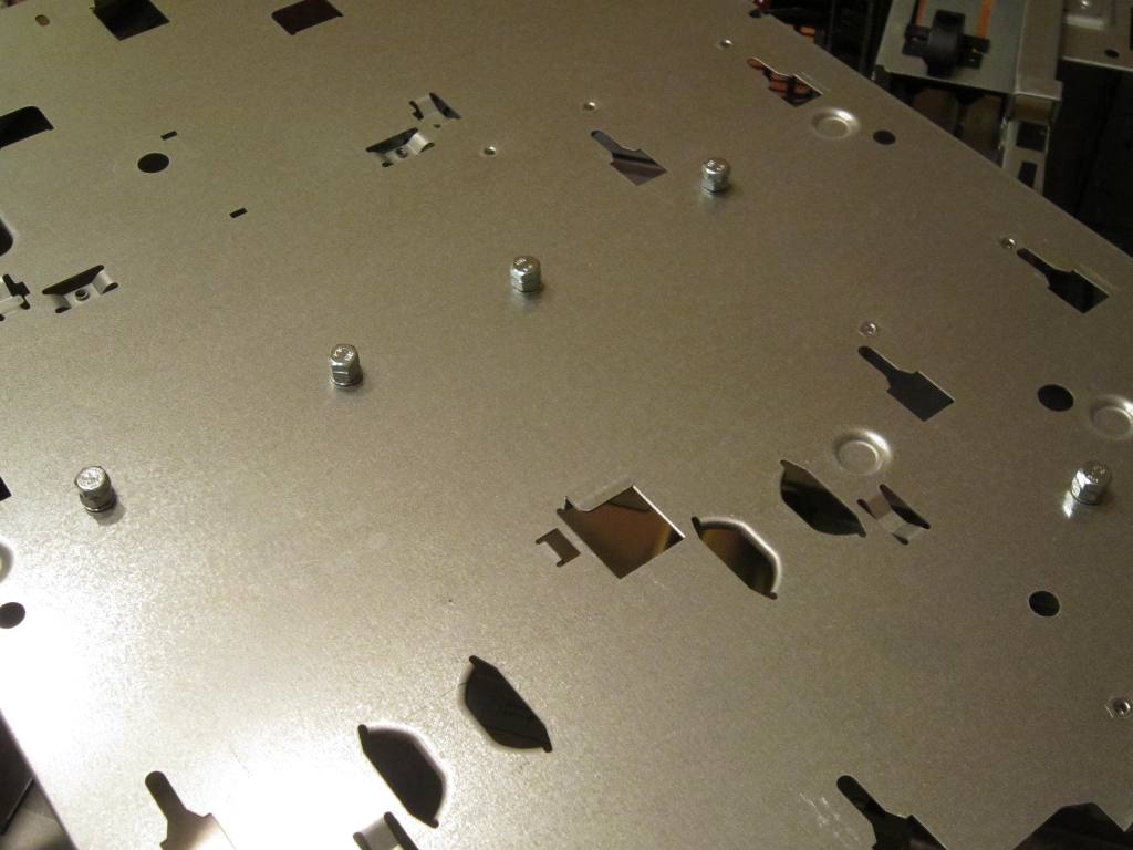
Remove all the internal components - only requires a screwdriver. The plastic back grille is held on by screws and easily removed. The black back panel however is held on by rivets and these have to be drilled out.
0JT001_zps319f81f6.jpg


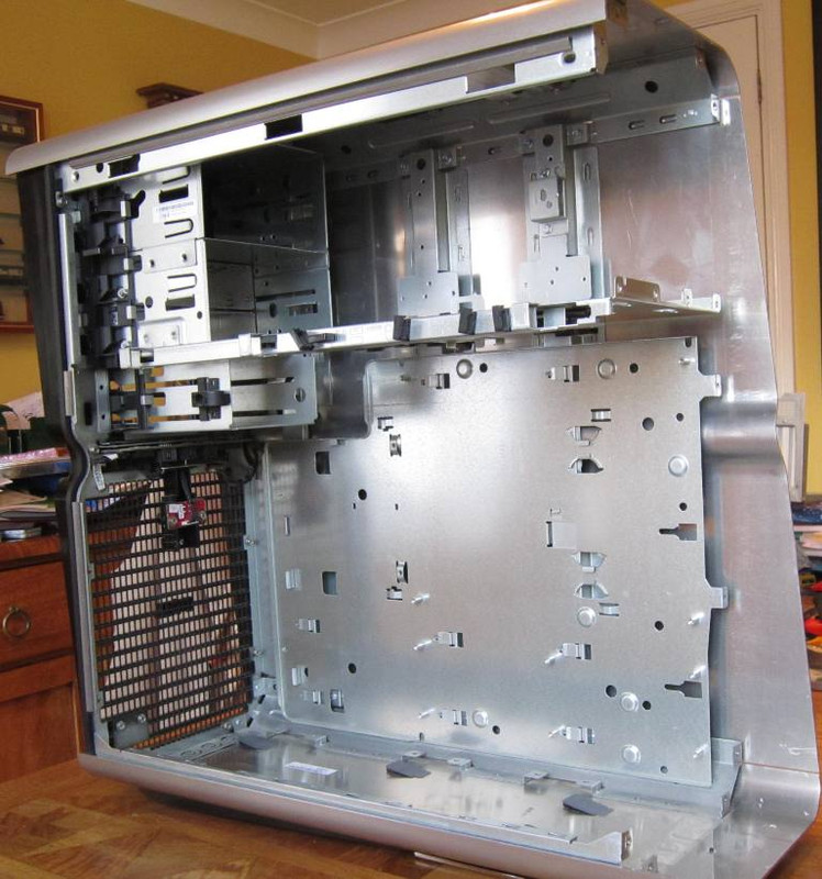
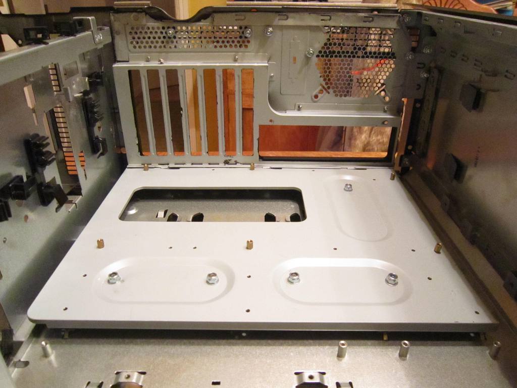
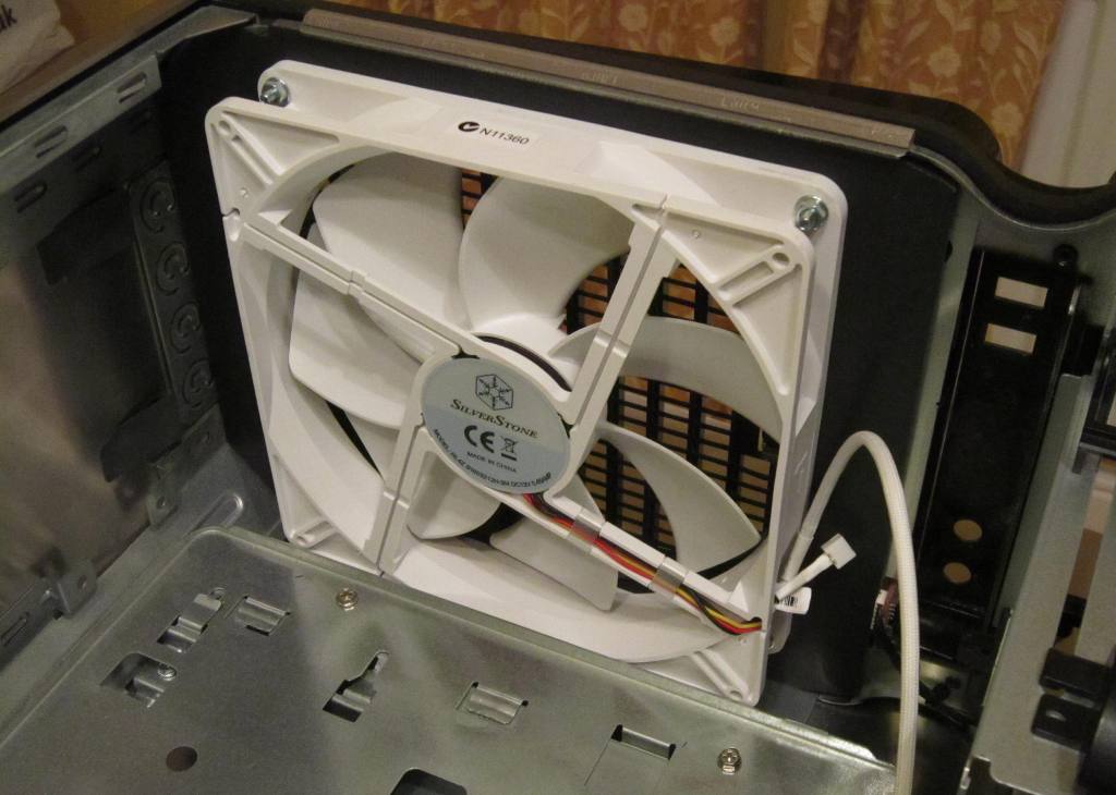
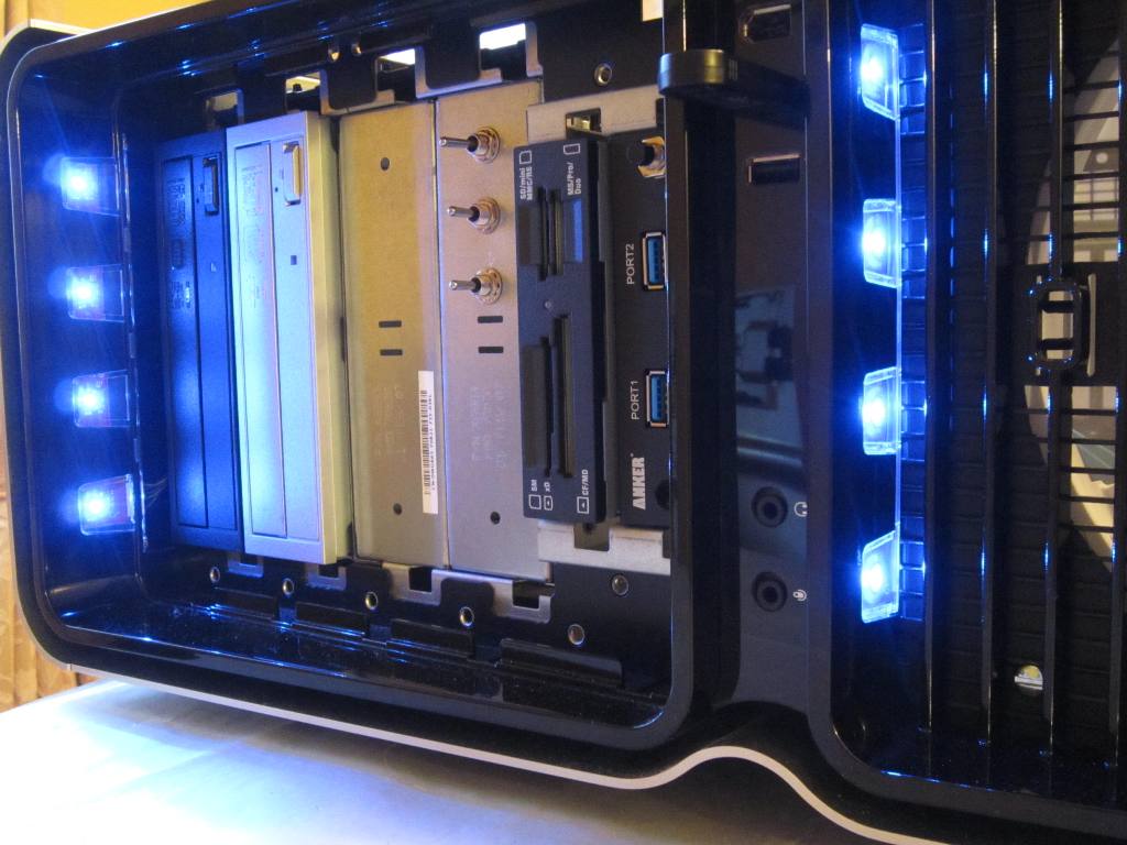
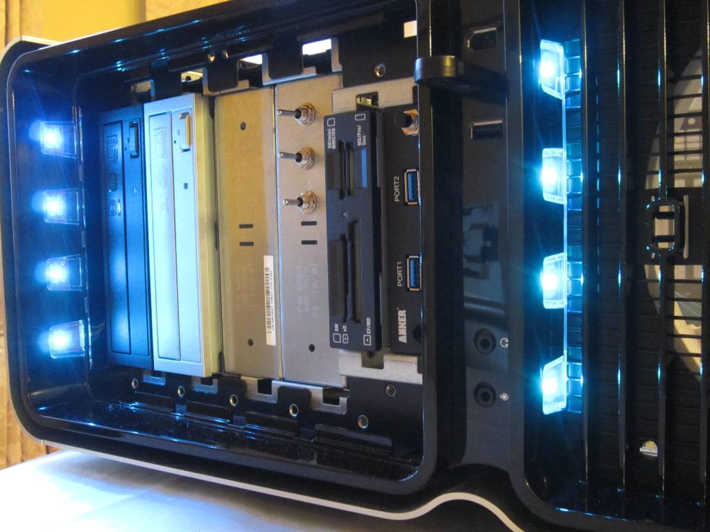
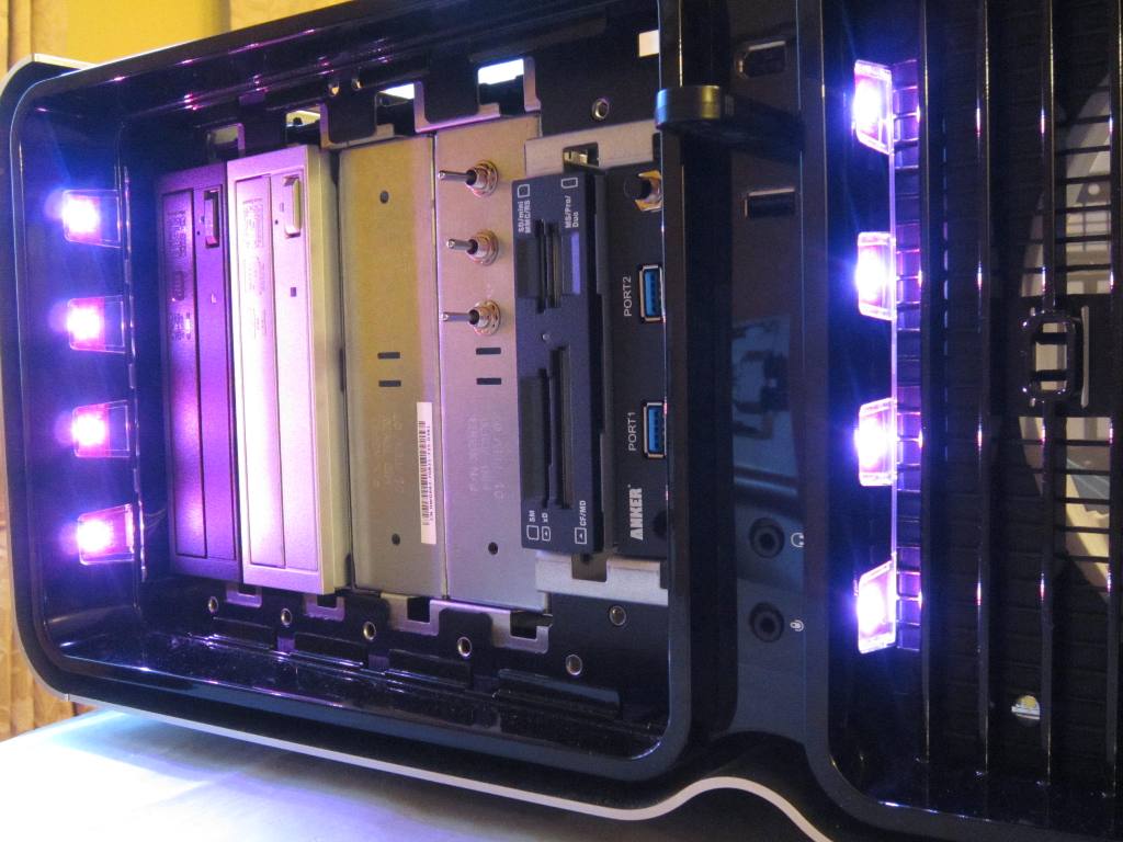
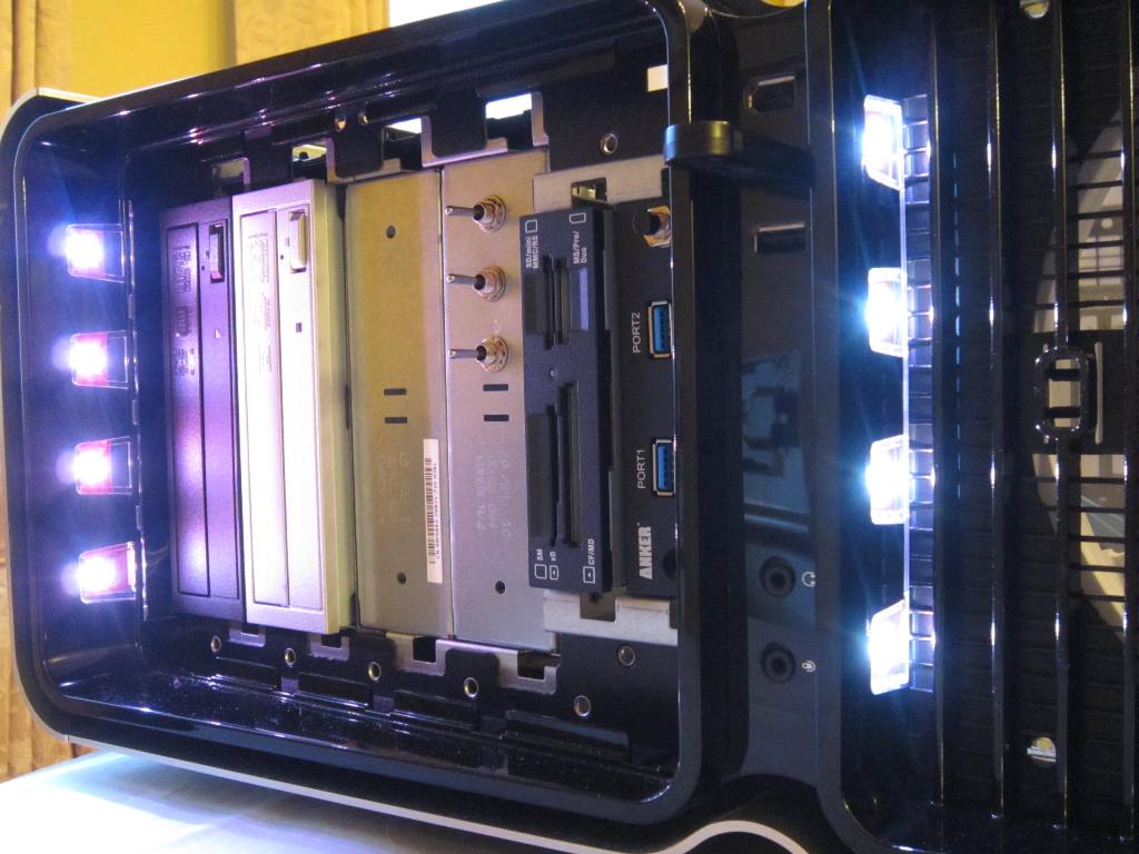
Everything at the front can be left in place at this time including the grille + LEDs, front panel, drive bays etc.

0JT002_zpsf8baa4c5.jpg


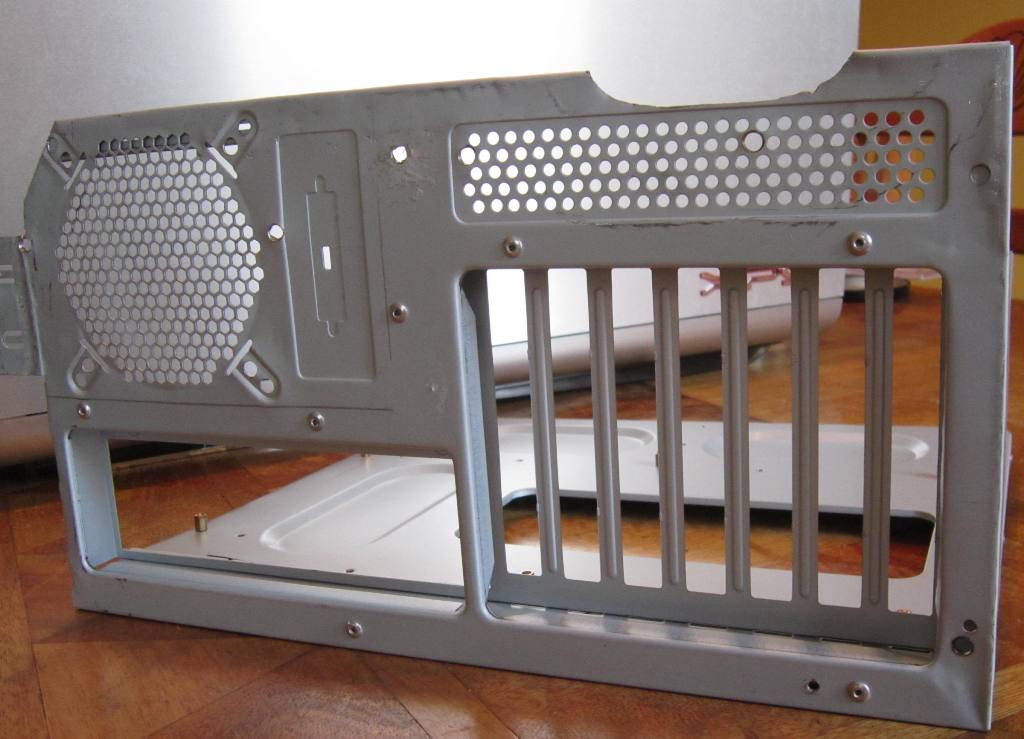
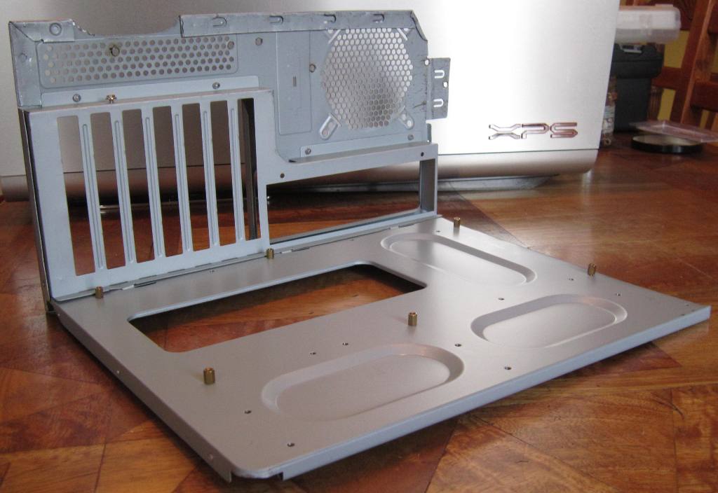
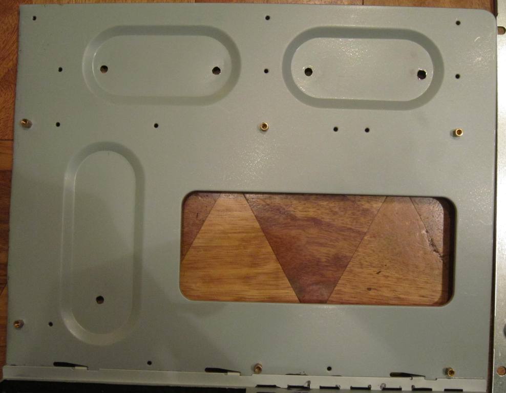
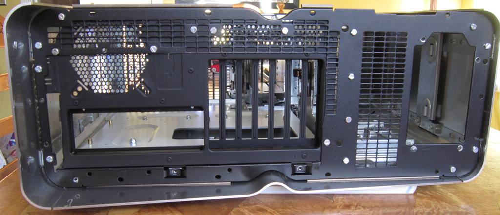
The next job is to modify the back panel. See next post..
 
Last edited:

John Tauwhare

Member
Dec 26, 2012
137
5
81
2. REMOVE PARTS OF THE BACK PANEL

The back panel is configured for a BTX motherboard so the openings for the slots are on the left and for the ports are on the right. These are swapped on an ATX motherboard. So the back panel has grille covering the slots and this has to be taken out. Everyone else seems to have done this with a Dremel. I'm not equipped with one of those but I do have a jigsaw. And on this job it takes only a few minutes.

0JT003_zps270375fb.jpg


The panel can now be positioned into the case and used to define the space for the new motherboard tray and back panel. The Dell panel has a horizontal flange all along the bottom which looked very difficult to remove; so I left it in place. It also had a vertical piece which was going to get in the way but I managed to get the jigsaw to cut it away - the bare metal scars are just visible on the top of the flange, on the left, in the photo.


0JT005_zps018bcb44.jpg
 
Last edited:
  • Like
Reactions: XMan

John Tauwhare

Member
Dec 26, 2012
137
5
81
3. GET AN ATX MOTHERBOARD TRAY AND BACK PANEL

Other converters have been able to get the Lian Li tray/panel, and it looks SO good. Really SHINY. But when I wanted one it was completely unobtainable :(. Plan B was to cut them out of an old case. A bit more work with the jigsaw produced this..

0JT006_zps461f30a2.jpg


NASTY; a bit disappointing really.

0_JT007_zps292897b0.jpg


But it was free, and it did fit. It rested neatly on the Dell's flange..

0JT008_zpsb97a15fb.jpg


Later on in the process I removed nearly everything above the ports and slots to improve airflow. In the end so much of it is hidden that the general crappiness of it doesn't matter.
 
Last edited:

John Tauwhare

Member
Dec 26, 2012
137
5
81
It looks a whole lot better with the back painted black. I sanded it down, then sprayed on undercoat, then a black satin finish.

0JT009_zpsa9a19ec2.jpg


In position, in the case, it's all beginning to take shape and the project seems possible.

0JT010_zpsf51b5cf6.jpg
 
Last edited:
  • Like
Reactions: gradoman

Face2Face

Diamond Member
Jun 6, 2001
4,100
215
106
Looking really good John. I just replaced my XPS Case with a Corsair 500R. Thinking about moving it to my server or giving it to a friend? Anyways, I look forward to seeing the final product.

Have Fun :)

Edit: The XPS case is now my new server case - I can't part with this thing of beauty..
 
Last edited:

John Tauwhare

Member
Dec 26, 2012
137
5
81
Thanks for your comment Face2Face. Your thread on the 720 mod was my best source of advice and inspiration! That Corsair 500R is an awesome case.
 

John Tauwhare

Member
Dec 26, 2012
137
5
81
4. INSTALL ATX MOTHERBOARD TRAY AND BACK PANEL

Because my new back panel rests on the flange the new tray has to be positioned higher than the Dell tray. My solution was to retain the Dell tray - both as a riser, and in case I wanted to keep the front fan assembly (which mounts onto the tray), and attach the new tray above it somehow. The cheap, de-mountable and robust attachment solution is bolts. This starts with 5 holes in the new tray, located in the recessed parts so the top bolt will be well below the motherboard.

0JT011_zps5c15ee1b.jpg


And I drilled 5 corresponding holes in the Dell tray (identifiable in the photo by the dents).

0JT012_zps6428531b.jpg


Then I inserted 5 x M5 25mm bolts into the tray from the bottom, with the length tuned down by one nut+washer (in the end 20mm bolts would have been ok).

0JT013_zps0caa711c.jpg


On the other side I attached secured those bolts with washers and nuts. Then put on another nut and washer and positioned them to give the correct spacing, frequently testing the position with the new tray until I had a right angle all along the back panel. Then the new tray was secured with washers and nylon topped nuts.. From the bottom the order would be: bolt, nut, washer, tray, washer, nut, gap, nut, washer, tray, washer, nut! It took me ages to think up that lot. Simple really.

0JT014_zps375f298f.jpg


And the new back panel was bolted into the Dell back panel. And it was bolted to the case.


0JT015_zpsba18df28.jpg


On the metal work bit, it's job done. Didn't seem that hard when I'd finished.

0JT016_zps10062507.jpg


Except that, as I'll explain later, I couldn't leave it alone, and kept coming back to it with tweaks.
 
Last edited:

John Tauwhare

Member
Dec 26, 2012
137
5
81
5. DELL PSU

I have the 750W PSU which is plenty powerful for my needs. I actually got a new 750W Seasonic PSU from Amazon but research (thanks Face2Face) showed how, with a bit of cable modification, the Dell unit could be retained, and I decided to go that route so the Seasonic gets RMA'd tomorrow.

0JT017_zpsc1f10fd3.jpg


Most of the plugs are standard and can be used in an ATX build but the 20 pin 12v connector (P2) for a BTX motherboard is surplus. However, an ATX motherboard requires an 8 pin 12v EPS for the CPU and this can be concocted out of the 20 pin. Indeed others have used surplus wires from the 20 pin to make 6 pins EPS connectors etc as well.

The OCZ FATAL1TY PSU that I got to power the rig I built out of the old XPS parts had way too many cables so it was the source of the 8 pin connector. I struggled at first to get the pins out but quickly learned the two-staple method of extraction: flatten one end of two staples then insert then either side of the pin pushing down the last few mm with small pliers, and pull the pin out.

0JT018_zpsf502bb46.jpg


The table below shows the pins I moved from the 20 pin connector into the 8 pin. There is no science to why I made that selection and any other mix of 12v rails and commons might be just as effective.

DCEPS8_zps34ac403f.png


Final result.

0JT019_zpsc423e0c3.jpg


Except that I later decided to power the front LEDs with 3.3v (quite adequate as it turns out) so I cut away the P14 peripheral connector, which has no other use, and screwed the wires into 2 x 3 connector blocks - putting 1+2+6 into one and 3 (COM) + 4 (3.3v) + 5 (5v) into the other.

 
Last edited:

John Tauwhare

Member
Dec 26, 2012
137
5
81
6. FANS - FRONT

I could have just reinstalled the Dell front fan but seeing how quiet and effective the Coolermaster HAF 922 case was, with its 2 x 19cm fans (one sucking at the front and the other blowing out of the top) I decided to go for a larger fan, as large as I easily could get that would fit. Mounting on the front panel seemed the easiest way of providing good support and avoiding having to fabricate brackets. And mounting on a baffle would help provide a pressure gradient.

Silverstone does 18cm fan products which seem to be good quality. From what I could see none are software controlled but one of them comes with a speed control pot. The SST FM181 uses ball bearings and can shift 150 cu ft/min at 1300 rpm (65 CFM when idling at 500 rpm) and that met my needs so I bought it for £20. Alas, it's white. But I think it looks ok.

For the baffle I got a sheet of 5mm black mounting board from a craft shop. I cut it to fit exactly into the space behind the case's lower front panel so it forms a (weak) seal, and I formed depressions to accommodate the various bolt heads.


Maybe it was a piece of design genius from Dell but it seemed like pure luck to me, that the fan mounting screw holes match exactly to the square openings in the front panel and grille. That spared me ALOT of hassle and made installation very simple. Though I had to sacrifice the ON switch.


Bolted in place with 4 x M4 screw bolts. Actually it is a snug fit behind the motherboard tray.

0JT023_zps6425d5fb.jpg


This photo shows progress so far. I've sawn away the back panel above the ports and slots. It is still securely held at the side and top but the exit airflow is less much restricted now.

 
Last edited:
  • Like
Reactions: gradoman

rsutoratosu

Platinum Member
Feb 18, 2011
2,716
4
81
Wow lots of work! I own a lot of dells in the past.. just too much work for me :) Nicely done
 

John Tauwhare

Member
Dec 26, 2012
137
5
81
Thanks rsutoratosu. There's lots more work to come but I've got two weeks off over the Christmas break and it's good to have a creative project to work on. The weather here is too awful to do much outside.
 

John Tauwhare

Member
Dec 26, 2012
137
5
81
7. MOTHERBOARD

Faced with either unpacking and installing all the nice shiny expensive bits and checking they fit, or fiddling with a soldering iron and the electronics, it was an easy choice. Well it was Christmas, and I wanted some toys.

Decided to switch to AMD this time to get value for money. The motherboard is a full ATX sized Gigabyte 990FXA UD3 rev 1.1 (rev 2.0 and 3.0 unavailable in UK) selected as being proven, reliable, and under £100 (£94).

0JT036_zpsc8510aa1.jpg


CPU is fx-8350. I expect to keep it for several years.

0JT037_zps511d4324.jpg


I researched (air) coolers for weeks but in the end the space constraints in all 3 dimensions made it a short short-list, and I went for the Xigmatek Aegir, mainly because it was available quickly and has lots of copper tubes so, in theory, ought to work well. I'd be interested in anyone else's opinions of it.

0JT038_zps9db3279b.jpg


RAM is 2 x 4Gb DDR3 @2400 with heatsinks.


No room for the cooler's fan at the front so I put it at the back.

0JT040_zps88fa6893.jpg


But the main fan blows directly onto the front of the heatsink. BTW, worth celebrating "mission accomplished" here, the conversion to ATX is a success!

0JT041_zps712d2e6c.jpg


Just enough space above the Xigmatek to get the case side cover on, only 1mm to spare.


0JT043_zps5d62ba9a.jpg


Good straight unimpeded airflow from front to back and out.


0JT044_zpsc8356708.jpg


I've got the electronics to tackle next.
 
Last edited:
  • Like
Reactions: gradoman

Eureka

Diamond Member
Sep 6, 2005
3,822
1
81
Wow, that is a nicely done job! I've always admired the Dell tower cases, never saw it as pratical though.

I like how this gives you a straight air tunnel for the CPU cooler. Now about that GPU..
 

Face2Face

Diamond Member
Jun 6, 2001
4,100
215
106
John - I love that motherboard - It looks sick. The project is coming along very good. I will say installing vented PCI covers or making your own for the case will help your GPU breathe a little, mostly if you have an non EE video card. These are the ones I purchased - they helped drop the temps on my 7950 by 5c.

http://www.newegg.com/Product/Produc...FQf0nAodDDkA8w
 
Last edited:

John Tauwhare

Member
Dec 26, 2012
137
5
81
Thanks Face2Face, pardon my ignorance but I had to Google what EE means! The video card I took out of the case was a 550Ti (the 8800 over expired a year ago) and I basically used it and ignored it. I don't have an understanding or any experience of GPU temps and cooling, but I aim to use this project to build that knowledge.

The video cards for this are 2 x GTX660s and I've checked and they have those vents at the back, as shown in your link, so I guess that's a good start?
 

John Tauwhare

Member
Dec 26, 2012
137
5
81
8. FRONT PANEL PCB DO-HICKEY

This component (not shown in the photo is that the ON switch screws into the bottom of it) can be used. I particularly wanted to keep the 2 x USB ports and the LEDs.

0JT026_zps6385cb9c.jpg


The USB ports pass through to the connector socket. I used the USB motherboard connector/cable from the tray donor case and transferred the 10 pin connector (shown yellow) from another cable onto the pins to make a double ended cable that fits (and works).

The six LEDs (4 x Diagnostics, 1 x LAN, 1 x HDD) are accessed through the 40 pin connector. Using a battery to test the pins I discovered which pins relate to the LEDs. This confirms more complete pin tables posted by others - though I did not go on to find the audio pins at this stage.

0JT027_zps8845710f.jpg


I identified the LEDs wires in the connector cable and brought them together with the +ve side of an HDD LED two wire cable and joined one of the GRNDS to the -ve side. Now all the LEDs work together as HDD LEDs.

0JT028_zps46dd7521.jpg


I have no use for the Firewire port and I may come back later to the audio. But for the moment I was able to reinstall this thing into the case, ready to plug into the motherboard.


9. ON SWITCH

Since the original ON switch assembly would not fit between the front panel and the main fan its function had to be relocated. I also wanted USB3 ports. I found this 3.5" unit (Amazon) for £10. There was space either side of the ports for small push-on switches (Maplin) which I added and connected to POWER and RESET motherboard cables. Sadly, I wasn't paying attention when I bought them and one of the original switches turned out to be push-off! But it's an easy fix.

0JT029_zpsc82ed72a.jpg


Ready for installation in a 3.5" bay.

0JT030_zpsbfa623a5.jpg
 
Last edited:

John Tauwhare

Member
Dec 26, 2012
137
5
81
10. LEDS

The 710 has 2 x sets of LEDs in the front grille with 5 wire cables from each that plug into the FRNT_PNL PCB. All seven colour combinations and OFF are available using all the binary numbers between 000 and 111 and can be managed using 3 ON/OFF toggle switches.


The problem is to join the 5 wire connectors with the 3 switches and power. I found a 10 pin male (Maplin), stripped the wire and joined each pair, giving 5 wires. This I labelled. The GRND pair is not used. The 3 x LED (black) wires go off to the 3 switches, and the POWER wire (red) I wrapped around the black ones. But at the switch end I looped the red wire back, together with another black wire (that joins all the switches) to produce a two wire power cable. This could be plugged and connected to any power source but my choice was to screw them into the ex-P14 connector block by the PSU, with the live going to the +3.3v orange wire. I believe using 5v is normal but 12v could cause burnout.


The switches fit into drilled holes in a 5.25" blank panel.

0JT032_zpsedf1d941.jpg


The 5 pin LED connectors have clips and protrusions but these can be easily removed with a sharp knife. Labelling helps identification.

0JT033_zps3f048d07.jpg


Power attached. Plugged in.


0JT025_zpsd1997690.jpg
 
Last edited:

John Tauwhare

Member
Dec 26, 2012
137
5
81
These are the seven colours:

Red

0JT035-Red_zps29dff5ea.jpg


Green

0JT035-Grn_zps01b159ba.jpg


Blue

0JT035-Blu_zps88fa80fc.jpg


Cyan

0JT035-Cya_zps13b51f6c.jpg


Purple

0JT035-Pur_zps782b8f3b.jpg


Yellow

0JT035-Yel_zps807dfa13.jpg


White


0JT035-Whi_zps2240265f.jpg


Relief they work! Other than fixing the RESET switch I'm done at the front here.
 
Last edited:

John Tauwhare

Member
Dec 26, 2012
137
5
81
11. INSTALLING THE SSD

For hard-drives I got two Toshiba DT01ACA050 500GB 3.5" units with no pretensions to high performance but good value. And an OCZ Vertex 4 128GB SSD.

0JT045_zps49828f7b.jpg


No problem mounting the HDDs but there was no obvious place to put the SSD. Others have put them in drive bays or beside the HDDs using velcro. I decided to drill two holes in the steel bulkhead and attach it, facing outwards, with screws.

0JT046_zpsd3d3a979.jpg


This makes it a nice visible feature and does a great job of concealing the mess of PSU wiring beneath.

 
Last edited:

Face2Face

Diamond Member
Jun 6, 2001
4,100
215
106
Thanks Face2Face, pardon my ignorance but I had to Google what EE means! The video card I took out of the case was a 550Ti (the 8800 over expired a year ago) and I basically used it and ignored it. I don't have an understanding or any experience of GPU temps and cooling, but I aim to use this project to build that knowledge.

The video cards for this are 2 x GTX660s and I've checked and they have those vents at the back, as shown in your link, so I guess that's a good start?


Awesome job on the LEDs and SSD, everything is coming together very nicely. My previous post is basically about making sure you have enough fresh cool air to feed and cool your GPU's. Depending on your load temps you may need to install another fan in front of your GPU's in order to keep them cool. In my case I had to install the vented PCI covers and mount a 120MM fan in front of my 7950. My 7950 is not a EE card and was "reusing" the hot air it was exhausting. That's why I needed another fan to supply cold air and push the hot air past the card and through the vented PCI covers. You may not have any issues with cooling your gpu's?
 

John Tauwhare

Member
Dec 26, 2012
137
5
81
12. INSTALLING GRAPHICS CARDS AND TIDYING UP INSIDE

All that remains on the inside is to install the graphics cards and finish connecting and tidying the wiring. I know a single graphics card would have been simpler and more sensible but I've never tried two and this is my chance to learn first-hand about SLI. The PNY Geforce GTX 660 2Gb were very competitively priced at £150 (Amazon) so I've got a pair of those. I don't actually need that much video processing power so in due course I'll move one of them into the Coolermaster box to replace the 550Ti and see how it runs with the QX6700.

0JT048_zps4c5840c9.jpg


A few views..

0JT049_zps7f018282.jpg


0JT050_zpsae220f6b.jpg


0JT051_zpscede9483.jpg


0JT052_zpsa26093a4.jpg


Lots of empty space!
 
Last edited:

John Tauwhare

Member
Dec 26, 2012
137
5
81
13. BACK PLASTIC GRILLE

This looked like being a messy job so I left it to last. The slots and ports parts of the grille have to be removed, trimmed and swapped. I made the cuts with my jigsaw, trimmed the ends with a sharp knife and metal file. (Note: unable to get these photos to all have the same orientation, sorry)

0JT053_zps89d5e1f2.jpg


This is how the main parts look swapped over but before I've removed the top bits from the ports end.

0JT054_zps4029c9f8.jpg


I put it together with 5 minute epoxy.

0JT055_zpsb6dba629.jpg


After doing the job it seemed ok but in retrospect I could have used a better method. The plastic cuts easily and very quickly with cutting pliers and leaves less bits to trim, so I should have used those for all the cuts. It's better to make the first cuts as close as possible to the edge/surround and then trim to length required. The stumps along the edge can then be filed right back to the edge. Then the grille parts connect with glue direct to the edge. This means the glue blobs are at the edge and are virtually invisible, not the case when they are mid-span. The photo above illustrates this well.
Now the grille has to be attached to the case.

Before..

0JT056_zps6d2c2398.jpg


By this point I had acquired a riveter and replaced the screw bolts with rivets (I think the screws looked better).

After..

0JT057_zps9651b81b.jpg


Now the grille covers the bare hole above the I/O ports and provides a neat finish without significantly obstructing exhaust airflow. You can also see the exhaust ends of the GTX 660s and, on the right, the Silverstone front fan control pot.

It is secured with the original screws, from the back panel and into the grille surround, on the left-side (when upright) and top and to the right of the PSU but the other screw holes on the right-side (middle to bottom) are completely inaccessible. Not a great result, but it's well fitted and tight enough. And anyway going to spend the rest of its life against a wall, so it's not a big deal.

Phew, hardware done.
 
Last edited:

John Tauwhare

Member
Dec 26, 2012
137
5
81
14. COMPLETION

Finishing touch..


0JT058_zps586825d4.jpg


Off the dining room table and back where it belongs; powered up on my desk with the U3011, today (and hopefully for another 5 years?).

0JT062_zps3a46646e.jpg


It's been a challenging project, but I fitted it in over about 10 days during the Christmas break, so I can go back to work on Monday with my lovely Dell XPS 710 case reinstated as my main home PC. And get my life back.

Except that I been reading some of the other threads in AnandTech that have got me interested, and also worried. So, now the testing begins..
 
Last edited:

John Tauwhare

Member
Dec 26, 2012
137
5
81
Awesome job on the LEDs and SSD, everything is coming together very nicely. My previous post is basically about making sure you have enough fresh cool air to feed and cool your GPU's. Depending on your load temps you may need to install another fan in front of your GPU's in order to keep them cool. In my case I had to install the vented PCI covers and mount a 120MM fan in front of my 7950. My 7950 is not a EE card and was "reusing" the hot air it was exhausting. That's why I needed another fan to supply cold air and push the hot air past the card and through the vented PCI covers. You may not have any issues with cooling your gpu's?

Thanks (figured out how to /quote now) for the compliments. It's good to have the hardware side finished and I'm really pleased with the results, and now I can get some testing done this weekend.

But I've been following that "Observations with an FX-8350" thread, which happens to be running simultaneously with my case project, and is extremely informative (though it really itched the AMD v Intel debate; serious amount of trolling).

However, I'm obviously now concerned that at 100% load my CPU is not a 125W, but rather a 200W part. I knew I would be pushing the PSU limit at 100% CPU and GPU load; with 0% capacitor aging the Thermaltake Power Supply Calculator says I need 690W. Add 10% capacitor aging (enough? we are talking about a 5 year old made-in-china PSU here) gives 752W. Add another ~75W for the realistic FX-8350 TDP gives ~825W. Yikes!! Looks like loading the GPUs AND overclocking the CPU is completely off the menu.
 

John Tauwhare

Member
Dec 26, 2012
137
5
81
I'm going to test the FX-8350 temp at stock against variations in fan speed.

The EasyTune v6 utility that came with the board (Gigabyte 990FXA-UD3) ran once and now won't run even if I re-install it. So I've abandoned that. Other recommendations I've picked up are CoreTemp and CPU-z and Argus. CoreTemp won't run on the FX-8350. The CPU-z download programme gave me a load of parasite apps and no CPU-z. Argus, however, runs well.

First results are:
Ambient: 20degC, main-fan idling on LOW at 460 RPM

Idle: core 14, socket 27, CPUfanRPM 1255, GPUs at 31
with CPUfan at max
Prime95 (Small FFTs): core 36, socket 48, CPUfanRPM 2100, GPUs at 33
with CPUfan on auto
Prime95 (Small FFTs): core 38, socket 51, CPUfanRPM 1870, GPUs at 33
with CPUfan reduced to a whisper
Prime95 (Small FFTs): core 44, socket 55, CPUfanRPM 1255, GPUs at 33

Questions: is there a better load test for the FX-8350 and what should I use to load the GPU(s)?