Delidded my i7-3770K, loaded temperatures drop by 20°C at 4.7GHz

Page 22 - Seeking answers? Join the AnandTech community: where nearly half-a-million members share solutions and discuss the latest tech.

tweakboy

Diamond Member
Jan 3, 2010
9,517
2
81
www.hammiestudios.com
Your brave risking soo much opening the CPU wow you gurus are crazy.

ya a direct TIM wow. 20c very nice.. now open side of your case and it will drop another 10c hmmmm gl BTW That Ivy cant operate @ 5Ghz or it can and @ what voltage.
 

mrob27

Member
Aug 14, 2012
29
0
0
www.mrob.com
[...] at best your cooling efficiency will be close to, but never as good as, that of the people who just direct-die cool their CPUs but you will have taken your CPU on one hellish journey that even Intel won't dare take it on.

But at least you know Intel knows their chips can survive direct-die cooling because that is exactly how these same chips get cooled in laptops.

Yep -- and high-end dual-socket Xeon workstations too!

Upgrading and Analyzing Apple's Nehalem Mac Pro (Anand, 2009 July 13)

cpu.jpg

"No lid, all Nehalem."

Note Anand's trouble with getting the HSF mounted safely onto the replacement CPUs with heatspreaders. He had the reverse problem that the delidders have. I recommended he measure the distance in thickness (using a micrometer) and add spacers to the threaded bolts to mitigate the risk of overtightening.
 

Yuriman

Diamond Member
Jun 25, 2004
5,530
141
106
Did you 
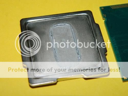
remove all the IHS adhesive (the black stuff) from both the PCB and the IHS?

When you have no CPU paste on the CPU or the IHS, can you freely spin your IHS? (meaning it is not making contact with the PCB)

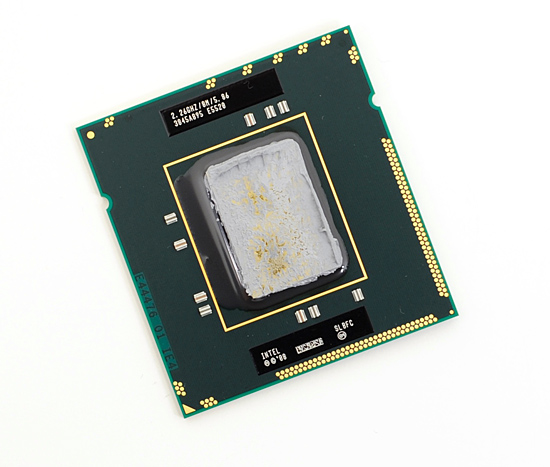
The next thing to be careful about is on the PCB where the black rectangle is with the writing on it, that is a raised area. Do not let your IHS slide up onto that when securing the socket retention bracket (you will notice the bracket pushes the IHS in the direction of the latch).

If the IHS slides up onto the bevel of that black rectangle then you will be creating a larger gap between the IHS and the CPU.

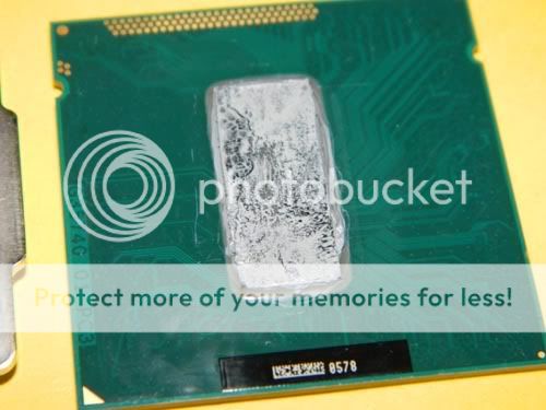
The other thing to check is the amount of TIM paste you are using and the type. If you have access to any other type you should at least try it to see if it makes a difference.

With my 3770k, by far and away the one thing that changes my operating temps the most is the gap between the IHS and the CPU.

The only time I see my 20C decrease in temps is if I let the IHS make direct contact with the die (with TIM inbetween of course). As soon as I do anything to lift the IHS off of the CPU, using metal shims or paper shims, the temperatures go crazy high.

So my advice to you is to get to know the gap between your CPU and IHS and figure out what it will take for you to eliminate it.

My next tests wiil be testing without the IHS. First though I have to repair my H100. I used that IC Diamond stuff for one test with the IHS and holy crap if it didn't corrode the bejesus out of the copper surface on my H100 and my IHS. It also scratched the CPU silicon die itself.

I'm rather pissed about that because I had my reservations and yet the IC diamond guy convinced me it wouldn't happen. But there it is, a big old scratch right on my chip and now the materials science education in me tells me exactly what that crack is going to do to the rest of my chip :( I've no one to blame but myself though, I knew better but I did it anyways.


I did get all of the black stuff off. The IHS spins freely on the die.

I remounted again, being careful not to let the IHS slide over the black area. On my last mount I had too little TIM between the die and the underside of the IHS it seems, but I went a little heavy this time and it doesn't seem to be making a difference. The paste hasn't had time to settle in, but my temperatures are almost exactly the same.

I really don't know what to say - I know there can't still be a gap between the die and IHS when I can clearly see light between the PCB and the IHS, it spins freely, and I've remounted 5 times now in an effort to get lower temps.

I'm going to pick up some sandpaper and lap the IHS tomorrow and see if it makes a difference, as it looks to be concave.

Any other suggestions?
 

BonzaiDuck

Lifer
Jun 30, 2004
15,699
1,448
126
It just occurs to me . . .

At least with a waterblock, you don't have the torque applied from the weight of a heatpipe cooler and attached fans.

Somehow, I don't understand why a direct-die contact for a waterblock would be much of a risk.
 

Idontcare

Elite Member
Oct 10, 1999
21,118
58
91
I did get all of the black stuff off. The IHS spins freely on the die.

I remounted again, being careful not to let the IHS slide over the black area. On my last mount I had too little TIM between the die and the underside of the IHS it seems, but I went a little heavy this time and it doesn't seem to be making a difference. The paste hasn't had time to settle in, but my temperatures are almost exactly the same.

I really don't know what to say - I know there can't still be a gap between the die and IHS when I can clearly see light between the PCB and the IHS, it spins freely, and I've remounted 5 times now in an effort to get lower temps.

I'm going to pick up some sandpaper and lap the IHS tomorrow and see if it makes a difference, as it looks to be concave.

Any other suggestions?

The lapping could be a difference. I lapped my IHS before I delidded it.
 

Yuriman

Diamond Member
Jun 25, 2004
5,530
141
106
IDC, I'm stumped.

img20121001232307.jpg


=(

Remount and try again? My temps are within margin of error of when I had the heatspreader on. Maybe I should lap the base of my waterblock and get some new thermal paste. Phobya HeGrease is supposed to be really good though.
 

Idontcare

Elite Member
Oct 10, 1999
21,118
58
91
When you take the IHS off after doing one of these tests, how thick is the TIM on the die and on the underside of the IHS? (after being squeezed by the mounting pressures)

Is the TIM so thin that you can you see the shiny silver of the cpu silicon?

i7-3770kdeliddedpostNT-H1test1.jpg


And on the IHS, is almost all of the TIM squeezed out of the region that makes contact with the die?

IHSdeliddedpostNT-H1test1.jpg
 

Yuriman

Diamond Member
Jun 25, 2004
5,530
141
106
I've tried varying amounts. On one mount I used so little TIM that it didn't actually spread entirely across the core, and I don't think the area it covered on the IHS<->WB side was as large as the die. I tried again with excess on both; it hasn't seemed to make too large a difference, a few C give or take.

This mount I believe is using just the right amount but I'm going to pull the WB off in a sec and try again.

I also disabled overclocking via the Intel utility and reset my bios settings, and then overclocked from bios. The resulting temperatures were approximately the same too.
 

dqniel

Senior member
Mar 13, 2004
650
0
76
I went a bit crazy today. I lapped the IHS down to the copper and my ZT-10D down to the copper. Then I applied Coollaboratory Liquid Ultra to the die and the underside of the IHS, popped it together with some Permatex RTV silicone, and applied Liquid Ultra between the IHS and the ZT-10D. Load temps at 4.5Ghz 1.232v during Prime Blend are ~44-52-47-49 after about ten minutes. We'll see how high they get during the smaller FFT portion and I'll update with the max temperatures. Ambient is about 21C
 
Last edited:

Yuriman

Diamond Member
Jun 25, 2004
5,530
141
106
I wonder if perhaps I don't have enough mounting pressure. I'm shy with the screws though, especially with a bare die.

These springs were originally used to mount an SLK-947U and they're pretty stiff, and before I delidded I wasn't using screws at all...

Anyway I remounted and this time spread the paste over the core with the applicator that came with the Phobya HeGrease and it looks like I've actually shaved a few celcius from my load temps. At 4.4ghz + 1.208v I'm getting approximately 67/76/77/73, which is about what I'd expect knowing where the dark silicon is on the chip.

I wonder if maybe I just have a bum chip?
 

Yuriman

Diamond Member
Jun 25, 2004
5,530
141
106
I went a bit crazy today. I lapped the IHS down to the copper and my ZT-10D down to the copper. Then I applied Coollaboratory Liquid Ultra to the die and the underside of the IHS, popped it together with some Permatex RTV silicone, and applied Liquid Ultra between the IHS and the ZT-10D. Load temps at 4.5Ghz 1.232v during Prime Blend are ~44-52-47-49 after about ten minutes. We'll see how high they get during the smaller FFT portion and I'll update with the max temperatures. Ambient is about 21C

I've been using Prime small FTT's because it seems to produce higher temperatures. Using Prime Blend at 4.4ghz I get around 63/69/70/68.
 
Last edited:

dqniel

Senior member
Mar 13, 2004
650
0
76
I've been using Prime small FTT's because it seems to produce higher temperatures. Using Prime Blend at 4.4ghz I get around 63/69/70/68.

You're definitely right. I've just always used Prime Blend, and if you run it for about 30 minutes it'll get near the same maximum temperatures as small FFT testing. I think it's because it runs nearly the same test once it "cycles" to the next iteration.

Anyway, I'm sticking with 30 min of Prime Blend for consistency reasons. In the future, I'll probably just do small FFT only for quicker results.

Quick update:

So, I think the combination of popping the IHS, lapping down to copper on the IHS and HSF, and using Liquid Ultra in all areas of contact has given me phenomenal results. Knock on wood, but so far I seem to be about 20C+ lower under load from before popping the IHS, and about 10C lower from before switching to Liquid Ultra and lapping everything. IC Diamond was nice but Liquid Ultra seems to be on a whole different level, because I don't think the lapping alone caused a 10C difference. I'll take upper 40s and mid 50s at 4.5Ghz/1.232v on air cooling any day!
 
Last edited:

dqniel

Senior member
Mar 13, 2004
650
0
76
It's been about three weeks since I put IC Diamond between the core and the IHS, and load temperatures are still vastly improved over the stock solution. I will update my old post in a moment to show details-

Thermal Cycling/TIM Failure Test

System Info:

3570K Delidded with IC Diamond between the die and IHS
ZT-10D HSF with Arctic Silver Ceramique between the IHS and the HSF
4.5Ghz @ 1.232v (after vdroop)

Delidded and IC Diamond applied 8/29/2012

After one week:
(9/4/2012)

Ambient temp - 25C
3570K max temps after Prime "blend" for 30 minutes - 67C, 76C, 74C, 73C

After three and a half weeks:
(9/22/2012)

Ambient temp - 22C
3570K max temps after Prime "blend" for 30 minutes - 62C, 72C, 71C, 69C

After about five weeks:
(10/1/2012)

Ambient temp - 22C
3570K max temps after Prime "blend" for 30 minutes - 62C, 72C, 70C, 69C


After lapping IHS and HSF base down to the copper and using Coollaboratory Liquid Ultra in all areas of contact:
(10/2/2012)

Ambient temp - 21C
3570K max temps after Prime "blend" for 30 minutes - 52C, 61C, 56C, 59C :eek:

More results to come...

Updated for final the IC Diamond run and the lapping/Liquid Ultra application.
 

Idontcare

Elite Member
Oct 10, 1999
21,118
58
91
I wonder if perhaps I don't have enough mounting pressure. I'm shy with the screws though, especially with a bare die.

These springs were originally used to mount an SLK-947U and they're pretty stiff, and before I delidded I wasn't using screws at all...

Anyway I remounted and this time spread the paste over the core with the applicator that came with the Phobya HeGrease and it looks like I've actually shaved a few celcius from my load temps. At 4.4ghz + 1.208v I'm getting approximately 67/76/77/73, which is about what I'd expect knowing where the dark silicon is on the chip.

I wonder if maybe I just have a bum chip?

Yeah we definitely cannot forget that this is all "YMMV" stuff we are playing with here.

That said, easy way to test if your mounting pressure is too low is to fire up a session of IBT (or prime95 small fft) and while you watch your screen for the temperature readout slowing unscrew the bolts ever slightly (1/4 turn max per iteration).

Unscrew them first and watch the temps start to rise. When you get a feel for how quickly (or slowly) the temps rise as you ever so slightly decrease the mounting pressure then you can reverse the process and start tightening the mounting bolts 1/4 turn each and watch the temps fall in real-time.

You will get to a point where the temps don't decrease anymore. That is when it is as tight as it needs to be.

(I have done this and it does work)
 

Yuriman

Diamond Member
Jun 25, 2004
5,530
141
106
After letting it Prime a while I slowly cranked the screws down until the springs fully compressed, and gave them a half turn beyond that. I saw no improvement in temperatures so I backed off about 2 turns, and saw no rise in temperatures.

On the bright side, it looks like I'm stable at a very slightly lower voltage than I was after delidding and reapplying the paste under the lid. I'll see if I can take it lower still.

I can't remember if you touched on this earlier in the thread, have you played with PLL voltage?
 

Idontcare

Elite Member
Oct 10, 1999
21,118
58
91
Well that rules the mounting out then. Bummer.

I have no experience with the PLL voltage. I've seen some people report that they had to tweak it in order to get certain clockspeeds but that has never been necessary for me. Not sure why, maybe it is like LLC and it comes down to the quality/design of the mobo?
 

dqniel

Senior member
Mar 13, 2004
650
0
76
My overclocking stability remains about the same whether the vPLL is at default or overvolted significantly. The only time I notice even a minor enhancement for overclocking is above like 4.8Ghz, in which case vPLL needs a bump.
 

Yuriman

Diamond Member
Jun 25, 2004
5,530
141
106
I took PLL voltage down to 1.586v and it looks like it was good for ~1-2c improvement (close to margin of error) at no cost to stability so I'm going to leave it there.

I played with other voltages, bringing them up and down, and saw no significant change.

I think the next thing I'll try is lapping the base of my waterblock, but I probably won't get around to it until Thursday night.
 

Ed1

Senior member
Jan 8, 2001
453
18
81
I took PLL voltage down to 1.586v and it looks like it was good for ~1-2c improvement (close to margin of error) at no cost to stability so I'm going to leave it there.

I played with other voltages, bringing them up and down, and saw no significant change.

I think the next thing I'll try is lapping the base of my waterblock, but I probably won't get around to it until Thursday night.

was yours cpu PLL around 1.8v stock ?
 

Rvenger

Elite Member <br> Super Moderator <br> Video Cards
Apr 6, 2004
6,283
5
81
I noticed with these chips, the motherboard can play a role in heat too. I went from an Asrock Z77 Extreme 4 to a Gigabyte Z77 UD5H, temps dropped 12c and I am even running higher voltage. My max temp used to be 83c now its 71c.
 

BonzaiDuck

Lifer
Jun 30, 2004
15,699
1,448
126
Updated for final the IC Diamond run and the lapping/Liquid Ultra application.

Once again, thanks for your periodic updates to this.

I think your temperature gains are distributed among two or three causes: First, the Liquid Ultra; second, the lapping; and if there's a third, it would be use of the Liquid Ultra on both points of contact.

The remaining question will be whether the Coollaboratory product adds a portion of whatever risk Intel was trying to avoid with their fluxless solder. "We -- whose processors could easily die -- salute our chances of buying a replacement."

It seems amazing that five weeks passed so quickly. But your tests also suggest to me that the IC Diamond provides a stable solution: compensating for the difference in ambients, your results show absolutely no change.

If I chose to worry about some "risk" using the Liquid Pro, I'd still lap surfaces to bare copper, use the diamond paste for the silicon-die contact, and apply the liquid-ultra/pro (whatever) to the IHS and HSF-base.

If I thought the bare (and perfectly flat) copper surfaces were worth as much as a 10C improvement, temper that with a more conservative guess of around 5C (assuming both surfaces treated). For the single interface between HSF and IHS, figure at most 2 to 4C over the use of diamond paste. But maybe it isn't possible to apportion the effects by some linear addition. Can't say for sure.
 

dqniel

Senior member
Mar 13, 2004
650
0
76
Yep, no way of knowing since I didn't bother to do testing in incremental steps. That would have been a huge pain and would have added a lot of time spent taking things apart and putting them back together repeatedly. Also, I would have had to use more IC Diamond and that stuff isn't cheap.