• We’re currently investigating an issue related to the forum theme and styling that is impacting page layout and visual formatting. The problem has been identified, and we are actively working on a resolution. There is no impact to user data or functionality, this is strictly a front-end display issue. We’ll post an update once the fix has been deployed. Thanks for your patience while we get this sorted.

Question ATX PSU shuts off when load attached to ATX wires

s355

Junior Member
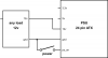
This circuit shuts off almost immediately.

1622563056560.png
This circuit runs perfectly, even with no load on the Molex.

FFIaT.png

Is my PSU dead? If not, how do I fix it?

After the first circuit shut off, I could reset it by turning the POWER switch off and on.
 

Attachments

  • 1622563056560 (1).png
    1622563056560 (1).png
    21.3 KB · Views: 6
Last edited:
1) Your power supply sounds dead

2) As mindless1 already said, your pictures do NOT open. You have to be a member of allaboutcircuits to see them. Just upload them as normal pictures here.
 
1) Your power supply sounds dead

2) As mindless1 already said, your pictures do NOT open. You have to be a member of allaboutcircuits to see them. Just upload them as normal pictures here.
See it now. The images were reuploaded.
 
Make/model of psu might help, or might not.

Assuming you are talking about the same PSU in both pics, it is probably shutting down from overvoltage protection because you don't have a load on the 5V rail. This is consistent with being able to retry by disconnecting power to reset it.

It's a result of group regulation, or less likely an aggressive green design where there is practically no load (resistor) on other rails, more often the case with PSU purpose built for a specific OEM app.
How does the second circuit work with no load on the ATX wires?
 
^ It depends on how the PSU is designed. In the most basic, old school design, the SMPS IC has an internal voltage reference, then the output of at least one but usually two or more rails (12V and 5V in this case) has a feedback to the IC going through a pair of resistors as a voltage divider to make the target output (whether 12V or 5V) get pulled down to the IC's reference voltage but there is an internal (or external set with a discreet component, you'd need to check the IC datasheet) failsafe if the voltage exceeds the limit.

The simplier way to put it is "IF" you have the most basic old PSU design described above, you could reduce the value of the resistor in the 5V feedback loop going to ground as the pull down to reduce that voltage within acceptable limits, OR easier would be just put a dummy load on the 5V rail for example a single-digit ohms power resistor, or just use a different PSU with independent rail regulation.
 
Back
Top