Discussion Apple Silicon SoC thread

Page 113 - Seeking answers? Join the AnandTech community: where nearly half-a-million members share solutions and discuss the latest tech.

Eug

Lifer
Mar 11, 2000
23,579
992
126
M1
5 nm
Unified memory architecture - LP-DDR4
16 billion transistors

8-core CPU

4 high-performance cores
192 KB instruction cache
128 KB data cache
Shared 12 MB L2 cache

4 high-efficiency cores
128 KB instruction cache
64 KB data cache
Shared 4 MB L2 cache
(Apple claims the 4 high-effiency cores alone perform like a dual-core Intel MacBook Air)

8-core iGPU (but there is a 7-core variant, likely with one inactive core)
128 execution units
Up to 24576 concurrent threads
2.6 Teraflops
82 Gigatexels/s
41 gigapixels/s

16-core neural engine
Secure Enclave
USB 4

Products:
$999 ($899 edu) 13" MacBook Air (fanless) - 18 hour video playback battery life
$699 Mac mini (with fan)
$1299 ($1199 edu) 13" MacBook Pro (with fan) - 20 hour video playback battery life

Memory options 8 GB and 16 GB. No 32 GB option (unless you go Intel).

It should be noted that the M1 chip in these three Macs is the same (aside from GPU core number). Basically, Apple is taking the same approach which these chips as they do the iPhones and iPads. Just one SKU (excluding the X variants), which is the same across all iDevices (aside from maybe slight clock speed differences occasionally).

EDIT:

Screen-Shot-2021-10-18-at-1.20.47-PM.jpg

M1 Pro 8-core CPU (6+2), 14-core GPU
M1 Pro 10-core CPU (8+2), 14-core GPU
M1 Pro 10-core CPU (8+2), 16-core GPU
M1 Max 10-core CPU (8+2), 24-core GPU
M1 Max 10-core CPU (8+2), 32-core GPU

M1 Pro and M1 Max discussion here:


M1 Ultra discussion here:


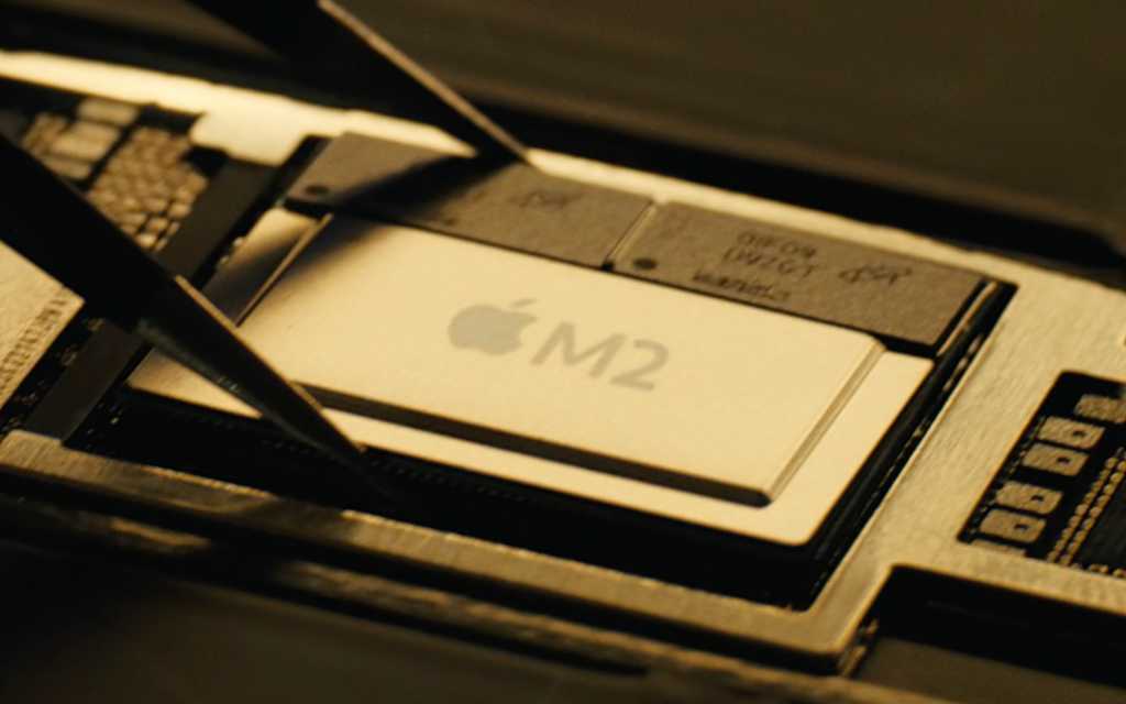
M2 discussion here:


Second Generation 5 nm
Unified memory architecture - LPDDR5, up to 24 GB and 100 GB/s
20 billion transistors

8-core CPU

4 high-performance cores
192 KB instruction cache
128 KB data cache
Shared 16 MB L2 cache

4 high-efficiency cores
128 KB instruction cache
64 KB data cache
Shared 4 MB L2 cache

10-core iGPU (but there is an 8-core variant)
3.6 Teraflops

16-core neural engine
Secure Enclave
USB 4

Hardware acceleration for 8K h.264, h.264, ProRes

M3 Family discussion here:

 
Last edited:

Doug S

Platinum Member
Feb 8, 2020
2,191
3,376
136
IMO, it's not overkill. This is not a bus to connect single purpose chiplet to common memory.

This is a bus to let the M1 Ultra act as if it is one big chip containing all the parts of both SoCs. All the GPU units work together, the caches work together, the NPUs work together, the external I/O works together, the media ecoders work together, without any NUMA or SLI issues. When connected it really is like one big chip and that needs a connection to everything at high speed and low latency just as if it were all on the same chip.

It's pretty freaking amazing.


I never said it was only to connect memory, but when cores "work together" their bandwidth they are able to consume talking to each other is bounded by the memory bandwidth between them where they meet. L2/L3 for chips which use a cluster design where cores share an L2, or top level cache for designs where they share a cache. In the M1 we know the SLC bandwidth is unfortunately less than the DRAM bandwidth, because neither the CPU cluster (topping out at around 210 GB/sec IIRC) or the GPU cluster (topping out at around 330 GB/sec) can match the 400 GB/sec the M1 Max DRAM is capable of delivering. We know it isn't overhead related since a single CPU core can consume almost exactly the 100 GB/sec provided on the regular M1 - the SLC is no bottleneck there. 2.5 TB/sec is so far above the capability of at least the M1 generation it is massive overkill for the M1 Ultra.

Whether it is overkill for the M2 depends on what improvements are made to eliminate the bottlenecks that limit the M1 Max's ability to exploit the full bandwidth. It isn't like they couldn't go higher than 10,000 I/Os and/or clock it higher if they need more bandwidth. But there's no way the M1 Ultra needs anything like that much bandwidth between chips. The cores don't have the performance necessary to consume data at that rate even in a worst case scenario where all data is located on the wrong chip.
 

Doug S

Platinum Member
Feb 8, 2020
2,191
3,376
136
Not only does that displace the memory chips which are positioned adjacent to the appropriate chip, but it also implies the only bandwidth that matters is memory bandwidth.

In order for the chips to function to software as a monolithic die is for the throughput from every core to every other core to be uniform, or within margins. Considering cache can run in the TB/s range, you can't split that bus up to more than 2 chips without the cache taking a severe bandwidth hit.

I significantly doubt more than two chips on a package is in the cards for this design.

You're assuming the only SoC to LPDDR layout they can use is the one they use now. The iPhone stacks the LPDDR on top of the SoC, if the memory chips weren't in the way that's not a problem, though I'm not sure about the limits of that stacking.

Though come to think of it since they need an additional routing layer in the interposer anyway they could do the back to back layout of the M1 Ultra for two SoCs, and then put the other two SoCs on the other side of the interposer. You'd mount a heatsink/fan on each side, sandwiching the interposer and SoCs/LPDDR in between. The interposer is essentially the "motherboard" of Apple Silicon Macs, and while double sided motherboards aren't common in PCs they have been used in higher end machines and I certainly wouldn't be surprised if Apple did it if they felt it was the best solution for them.
 

LightningZ71

Golden Member
Mar 10, 2017
1,627
1,898
136
I never said it was only to connect memory, but when cores "work together" their bandwidth they are able to consume talking to each other is bounded by the memory bandwidth between them where they meet. L2/L3 for chips which use a cluster design where cores share an L2, or top level cache for designs where they share a cache. In the M1 we know the SLC bandwidth is unfortunately less than the DRAM bandwidth, because neither the CPU cluster (topping out at around 210 GB/sec IIRC) or the GPU cluster (topping out at around 330 GB/sec) can match the 400 GB/sec the M1 Max DRAM is capable of delivering. We know it isn't overhead related since a single CPU core can consume almost exactly the 100 GB/sec provided on the regular M1 - the SLC is no bottleneck there. 2.5 TB/sec is so far above the capability of at least the M1 generation it is massive overkill for the M1 Ultra.

Whether it is overkill for the M2 depends on what improvements are made to eliminate the bottlenecks that limit the M1 Max's ability to exploit the full bandwidth. It isn't like they couldn't go higher than 10,000 I/Os and/or clock it higher if they need more bandwidth. But there's no way the M1 Ultra needs anything like that much bandwidth between chips. The cores don't have the performance necessary to consume data at that rate even in a worst case scenario where all data is located on the wrong chip.
Isn't there an additional functional unit on the M1 series though? The NPU isn't exactly ignoring memory. If they have a way of clustering the two GPU segments, perhaps they are also clustering the NPU. I also suspect that Apple is attempting to keep the local cache on the CPU clusters coherent across the two clusters so that they can avoid NUMA issues. I can't imagine that Apple would throw silicon and money at intentionally over-provisioning memory bandwidth to the processor to such a degree. They could use slower, lower power memory chips if they had no use for the bandwidth. There's definitely something that's using the capacity.
 
  • Like
Reactions: scannall

Eug

Lifer
Mar 11, 2000
23,579
992
126

Doug S

Platinum Member
Feb 8, 2020
2,191
3,376
136
Isn't there an additional functional unit on the M1 series though? The NPU isn't exactly ignoring memory. If they have a way of clustering the two GPU segments, perhaps they are also clustering the NPU. I also suspect that Apple is attempting to keep the local cache on the CPU clusters coherent across the two clusters so that they can avoid NUMA issues. I can't imagine that Apple would throw silicon and money at intentionally over-provisioning memory bandwidth to the processor to such a degree. They could use slower, lower power memory chips if they had no use for the bandwidth. There's definitely something that's using the capacity.

I'm not sure whether they are clustering the NPU, or whether that's even particularly useful (i.e. since NPU tasks are already so highly parallel, I wonder if it makes much difference to have 2 NPUs of power 'n' vs one NPU of power '2n') but I guess we'll see once people start taking delivery of M1 Ultra systems.

Rather than worry about whether 2.5 TB/sec is too much or only adequate for two cores with more being required for additional cores, how about we compare it to existing implementations?

I googled a bit for AMD and Intel but didn't immediately find their chiplet to chiplet bandwidth number to compare with Apple's 2.5 TB/sec, at least not of the most recent stuff. I found a diagram at wikichip indicating Epyc (not sure of generation, I guess Zen 1?) had Infinity Fabric links of 42 GB/sec between chiplets in a four chiplet 32 core config. Even if that's been ramped up a lot in subsequent generations, that's still a fraction of Apple's. Anyone have data on the Zen 3, 4, or 5 Infinity Fabric links between chiplets? Or for whatever Intel's new mesh is called?

Likewise it was hard to find any data on GPUs, other than Nvidia's DGX-2, which has a 300 GB/sec bidirectional bandwidth between individual GPUs and Nvidia thinks that's good enough to sell a 12 GPU system for $400K! Chiplets for GPUs seem to be in their infancy, but maybe someone has seen some data there that can be compared?

So I will posit that unless others are doing a chiplet to chiplet bandwidth even remotely close to 2.5 TB/sec, it is hard to argue that Apple must have more in a four SoC system even after taking into account that Apple includes CPU, GPU, and NPU. Yes there are also some fixed function stuff like decoders but Apple states you get more of them with the Ultra, not the same number at twice the performance so there is no clustering there. Worst case they simply operate on memory attached to another SoC.
 

tomatosummit

Member
Mar 21, 2019
184
177
116
Likewise it was hard to find any data on GPUs, other than Nvidia's DGX-2, which has a 300 GB/sec bidirectional bandwidth between individual GPUs and Nvidia thinks that's good enough to sell a 12 GPU system for $400K! Chiplets for GPUs seem to be in their infancy, but maybe someone has seen some data there that can be compared?
The most similar one I can think of would be AMD's new mi200 gpgpu.
But I can't find any reliable numbers on it's interconnect. Only place that actually lists something is tom's but the paragraph is talking about the 8x 100gb/s infinity fabric links which should be ifop and not interchiplet.

But the interconnect on that would have to take into account the 1.6TB/s of memory on each chiplet so my guess would be that it's within that region and, if you were marketing inclined, claim double the number for bidirectional bandwidth.
 

Saylick

Diamond Member
Sep 10, 2012
3,082
6,170
136
The most similar one I can think of would be AMD's new mi200 gpgpu.
But I can't find any reliable numbers on it's interconnect. Only place that actually lists something is tom's but the paragraph is talking about the 8x 100gb/s infinity fabric links which should be ifop and not interchiplet.

But the interconnect on that would have to take into account the 1.6TB/s of memory on each chiplet so my guess would be that it's within that region and, if you were marketing inclined, claim double the number for bidirectional bandwidth.
https://www.anandtech.com/show/1705...i200-accelerator-family-cdna2-exacale-servers
With the additional IF links exposed by the OAM form factor, AMD has given each GCD 8 Infinity Fabric 3.0 links. As previously mentioned, 4 of these links are used to couple the two GCDs within an MI200, which leaves 4 IF links per GCD (8 total) free for linking up to hosts and other accelerators.

All of these IF links are 16 bits wide an operate at 25Gbps/pin in a dual simplex fashion. This means there’s 50GB/second of bandwidth up and another 50GB/second of bandwidth down along each link. Or, as AMD likes to put it, each IF link is 100GB/second of bi-directional bandwidth, for a total aggregate bandwidth of 800GB/second. Notably, this gives the two GCDs within an MI250(X) 200GB/second of bandwidth in each direction to communicate among themselves. This is an immense amount of bandwidth, but for remote memory accesses it’s still going to be a fraction of the 1.6TB/second available to each GCD from its own HBM2E memory pool.

If I'm interpreting the article correctly, it's 4 links between GCDs and each link can do 50 GB/s in each direction. That's 200 GB/s total in each direction, which is much lower than the HBM bandwidth. The GPU itself isn't really a chiplet design, and the fact that the OS recognizes each GCD as a separate GPU is consistent with that ideology.
 

Mopetar

Diamond Member
Jan 31, 2011
7,794
5,897
136
2000 points is on a 17% improvement over the M1. It seems reasonable to conclude that Apple could reach that through some combination of IPC and clock speed improvements.

I don't know what their usual performance improvements have been, but even if they're a bit under that on average it still doesn't put 17% outside of the realm of possibility.
 

ashFTW

Senior member
Sep 21, 2020
302
224
96
2000 points is on a 17% improvement over the M1. It seems reasonable to conclude that Apple could reach that through some combination of IPC and clock speed improvements.

I don't know what their usual performance improvements have been, but even if they're a bit under that on average it still doesn't put 17% outside of the realm of possibility.


Here are iPad 12.9” GB5 single and multi core scores over the years:

1st Gen (Sep 2015) with A9X: 637, 1194
2nd Gen (June 2017) with A10X Fusion: 833 (+31.8%), 2279 (+90.9%)
3rd Gen (Oct 2018) with A12X Bionic: 1145 (+37.5%), 4774 (+109%)
4th Gen (March 2020) with A12Z Bionic: 1121 (-2.1%), 4665 (-2.3%)
5th Gen (April 2021) with M1: 1706 (+52.2%), 7219 (+54.7%)

Average Gen-over-Gen performance is +30%, +63%.

When M2 comes out later this year, roughly 2 years after M1, greater than 17% single thread improvement is very plausible.
 
  • Like
Reactions: Mopetar

Eug

Lifer
Mar 11, 2000
23,579
992
126
+14% over M1 would be needed for M2 to breach 2000.
M1 single-core tops out around 1755.

Fanless MacBook Air gets 1756/7670.


Yes I could see that if it's indeed based on A16. Not so much if based on A15.

P.S. This was typed on a dual-core Mac mini that gets 770 single-core and less than 1700 multi-core. :p
 

Doug S

Platinum Member
Feb 8, 2020
2,191
3,376
136
So given that the M1 Max die is roughly square and 432 mm^2, that bottom edge is about 20 mm, in which over 10,000 I/Os are presented. That's one every 2 um along the edge.

We know TSMC can do really dense I/O pitches, the CoW technology AMD is using has a 0.9 um pitch on N7, and presumably an even smaller pitch on N5. I was looking at TSMC's portfolio and think this sounds closest to CoWoS-S though its uncertain. However I'm unsure whether any TSMC technology designed for an interposer/substrate allows for 10,000 I/Os along a 20mm edge, so they may use multiple rows at a looser pitch that connect to finer pitch RDLs in the interposer.

If so then tripling the interconnect in the M2 Max to support four SoC configurations is even easier. It would also be more likely they do the "sandwich" approach I previously suggested with two M2 Max dies on either face of the interposer. The interconnect between the two opposite dies on the same face would work as it does now, the interconnect between the dies on opposite faces / same side goes straight through TSV style, and the interconnect between opposite faces / opposite sides runs inside the interposer (i.e. the middle/third layer of the interposer) I suppose using CoW like AMD to directly stack two M2 Max dies would work also, though it may complicate things for the LPDDR.

I really wish Apple did ISSCC talks, hearing about the M1 Ultra and whatever they call what goes into the Mac Pro would be very interesting!
 
  • Like
Reactions: ashFTW

ashFTW

Senior member
Sep 21, 2020
302
224
96
Can someone shed more light on Apple vs Intel solution of connecting two die. Why are the SPR EMIB chiplets so big, and why is there such a large space on SPR chiplet (that requires PHY) devoted to interfacing with the EMIB chiplets. AAPL on the other hand uses a much smaller die area for connecting two die (without needing PHY?) with huge bandwidth. In the context of TSMC/Apple technology, is EMIB really “advance packaging”, as Intel likes to call it.
 

ashFTW

Senior member
Sep 21, 2020
302
224
96
If so then tripling the interconnect in the M2 Max to support four SoC configurations is even easier. It would also be more likely they do the "sandwich" approach I previously suggested with two M2 Max dies on either face of the interposer.
By the way, I absolutely LOVE this “sandwich” idea. Apple is very likely to do just that. It will require advance thermal solution on both sides of the mother board. IF implemented inside a Mac Studio like enclosure, it will need to be at least twice taller (maybe a perfect 7.7” cube!!) with double the power supply (800W?), and maybe beefier intake air vents.

PS: I can see a marketing slide with AS Mac Mini, Mac Studio, and Mac Pro all lined up next to each other, with the same design language, physically varying only in their height. Very Apple like messaging!
 
Last edited:

ashFTW

Senior member
Sep 21, 2020
302
224
96

M1 Ultra using Chip-on-Wafer-on-Substrate with Si interposer (CoWoS-S) technology, as also suggested by @Doug S above.

“In UltraFusion technology, by using die stitching (Die Stitching) technology, 4 masks can be spliced to expand the area of the interposer. In this method, 4 masks are exposed simultaneously and four stitched “edges” are generated in a single chip.

UltraFusion architecture interconnection technology (single-layer and multi-layer, refer to patent US 20220013504A1/US 20210217702A1.

Special optimization of six major technologies:

1) Low RC interconnect
2) Interconnect power consumption control
3) Optimize TSV
4) Capacitors integrated in the interposer (iCAP)
5) New thermal interface materials
6) Effectively improve packaging yield and reduce costs through Die-Stitching technology”

I’m now trying to find those Apple patents. Please post links if you find them before I do.

Here is one possible implementation of the “sandwich” idea from Apple patent.

1647140442417.png
 
Last edited:

eek2121

Platinum Member
Aug 2, 2005
2,883
3,859
136

Here are iPad 12.9” GB5 single and multi core scores over the years:

1st Gen (Sep 2015) with A9X: 637, 1194
2nd Gen (June 2017) with A10X Fusion: 833 (+31.8%), 2279 (+90.9%)
3rd Gen (Oct 2018) with A12X Bionic: 1145 (+37.5%), 4774 (+109%)
4th Gen (March 2020) with A12Z Bionic: 1121 (-2.1%), 4665 (-2.3%)
5th Gen (April 2021) with M1: 1706 (+52.2%), 7219 (+54.7%)

Average Gen-over-Gen performance is +30%, +63%.

When M2 comes out later this year, roughly 2 years after M1, greater than 17% single thread improvement is very plausible.

Ignore multicore numbers for a moment, let's talk single threaded performance.

From Wikichip:

TSMC original 7-nanometer N7 process was introduced in April 2018. Compared to its own 16-nanometer technology, TSMC claims its 7 nm node provides around 35-40% speed improvement or 65% lower power. Compared to the half-node 10 nm node, N7 is said to provide ~20% speed improvement or ~40% power reduction. In terms of density, N7 is said to deliver 1.6x and 3.3x improvement compared to N10 and N16 respectively. N7 largely builds on all prior FinFET processes the company has had previously. To that end, this is a fourth-generation FinFET, fifth-generation HKMG, gate-last, dual gate oxide process.

The A12X was built on N7. The A9x on N16, and the A10x on N10.

More from wikichip:

At a high level, TSMC N5 is a high-density high-performance FinFET process designed for mobile SoCs and HPC applications. Fabrication makes extensive use of EUV at Fab 18, the company’s new 12-inch GigaFab located at the Southern Taiwan Science Park. TSMC says that its 5-nanometer process is 1.84x denser than its 7-nanometer node. TSMC also optimized analog devices where roughly 1.2x scaling has been achieved. TSMC reported the density for a typical mobile SoC which consists of 60% logic, 30% SRAM, and 10% analog/IO, their 5 nm technology scaling was projected to reduce chip size by 35%-40%.

The M1 is built on N5.

The Original TSMC N4 process is a very small shrink from N5 (6%, there are sources, do some Googling).

N4P adds another 6% on top of N4.

That tells me IPC or perf/watt increases will be modest at best. In order to up the performance gain Apple will need to do one of the following:

  1. Increase core size, and therefore power consumption.
  2. Drastically improve the cores themselves. Note that MOST of their gains come from the process. If all 3 chips were ported to 5nm and compared at peak perf/watt today, the gains would be much more modest.
  3. Move to N3.
Option 1 is the most likely. Drop another M1 Ultra chip (for a total of 2x M1 Ultras) on a Mac Pro and profit. Option 2, though possible, is unlikely. Apple has already refined their current cores significantly. Let's look at option 3:

From AnandTech:
TSMC's N3 technology will provide full node scaling compared to N5, so its adopters will get all performance (10% - 15%), power (-25% ~ -30%), and area (1.7x higher for logic) enhancements that they come to expect from a new node in this day and age. But these advantages will come at a cost. The fabrication process will rely extensively on extreme ultraviolet (EUV) lithography, and while the exact number of EUV layers is unknown, it will be a greater number of layers than the 14 used in N5. The extreme complexity of the technology will further add to the number of process steps – bringing it toto well over 1000 – which will further increase cycle times.

So TSMC N3 is the next big jump from N5. I believe that Apples next big design overhaul will start with TSMC N3, therefore, you won't see it this year. You might see some minor to moderate improvements in the meantime, but nothing big. Multithreaded performance is different because they can throw more cores at the problem, just like Intel is doing.

We will see.
 

repoman27

Senior member
Dec 17, 2018
342
488
136
CoWoS-L looks like a much better fit for what Apple is using for M1 Ultra. Chip-last, because the dies are pretty big to begin with and chip-first probably wouldn't be economically feasible. Local silicon interconnect bridge to link the two dies, because the I/O for that is all concentrated into a small area so there's no need to do a full-size silicon interposer. Plus a redistribution layer to handle any additional fanout.
 

ashFTW

Senior member
Sep 21, 2020
302
224
96
Ignore multicore numbers for a moment, let's talk single threaded performance.

From Wikichip:


The A12X was built on N7. The A9x on N16, and the A10x on N10.

More from wikichip:


The M1 is built on N5.

The Original TSMC N4 process is a very small shrink from N5 (6%, there are sources, do some Googling).

N4P adds another 6% on top of N4.

That tells me IPC or perf/watt increases will be modest at best. In order to up the performance gain Apple will need to do one of the following:

  1. Increase core size, and therefore power consumption.
  2. Drastically improve the cores themselves. Note that MOST of their gains come from the process. If all 3 chips were ported to 5nm and compared at peak perf/watt today, the gains would be much more modest.
  3. Move to N3.
Option 1 is the most likely. Drop another M1 Ultra chip (for a total of 2x M1 Ultras) on a Mac Pro and profit. Option 2, though possible, is unlikely. Apple has already refined their current cores significantly. Let's look at option 3:

From AnandTech:


So TSMC N3 is the next big jump from N5. I believe that Apples next big design overhaul will start with TSMC N3, therefore, you won't see it this year. You might see some minor to moderate improvements in the meantime, but nothing big. Multithreaded performance is different because they can throw more cores at the problem, just like Intel is doing.

We will see.
Very nice analysis! We will see, indeed! :)
 

The Hardcard

Member
Oct 19, 2021
46
38
51
CoWoS-L looks like a much better fit for what Apple is using for M1 Ultra. Chip-last, because the dies are pretty big to begin with and chip-first probably wouldn't be economically feasible. Local silicon interconnect bridge to link the two dies, because the I/O for that is all concentrated into a small area so there's no need to do a full-size silicon interposer. Plus a redistribution layer to handle any additional fanout.

I would love to see details, but it appears that Apple has their own packaging process. There was some debate over whether M1 Ultra was one die or two - it appears the answer is both are correct.

M1 Max wafers are patterned to be lined up for Ultra and validation is done on wafer. If a pair passes testing they are cut out together as one piece of silicon. They then still have to be electrically connected with an interposer.

The Youtuber Max Tech referenced the Apple patents on this.
 

Doug S

Platinum Member
Feb 8, 2020
2,191
3,376
136

M1 Ultra using Chip-on-Wafer-on-Substrate with Si interposer (CoWoS-S) technology, as also suggested by @Doug S above.

“In UltraFusion technology, by using die stitching (Die Stitching) technology, 4 masks can be spliced to expand the area of the interposer. In this method, 4 masks are exposed simultaneously and four stitched “edges” are generated in a single chip.

UltraFusion architecture interconnection technology (single-layer and multi-layer, refer to patent US 20220013504A1/US 20210217702A1.

Special optimization of six major technologies:

1) Low RC interconnect
2) Interconnect power consumption control
3) Optimize TSV
4) Capacitors integrated in the interposer (iCAP)
5) New thermal interface materials
6) Effectively improve packaging yield and reduce costs through Die-Stitching technology”

I’m now trying to find those Apple patents. Please post links if you find them before I do.

Here is one possible implementation of the “sandwich” idea from Apple patent.

View attachment 58568


Great find on that article with the patent links! Where did you find the picture you linked with the interposer in the center? The article references three patents but I don't see that anywhere.

Apple patent US20220013504A1
Aople patent US20210217702A1
TSMC patent US20210305146A1

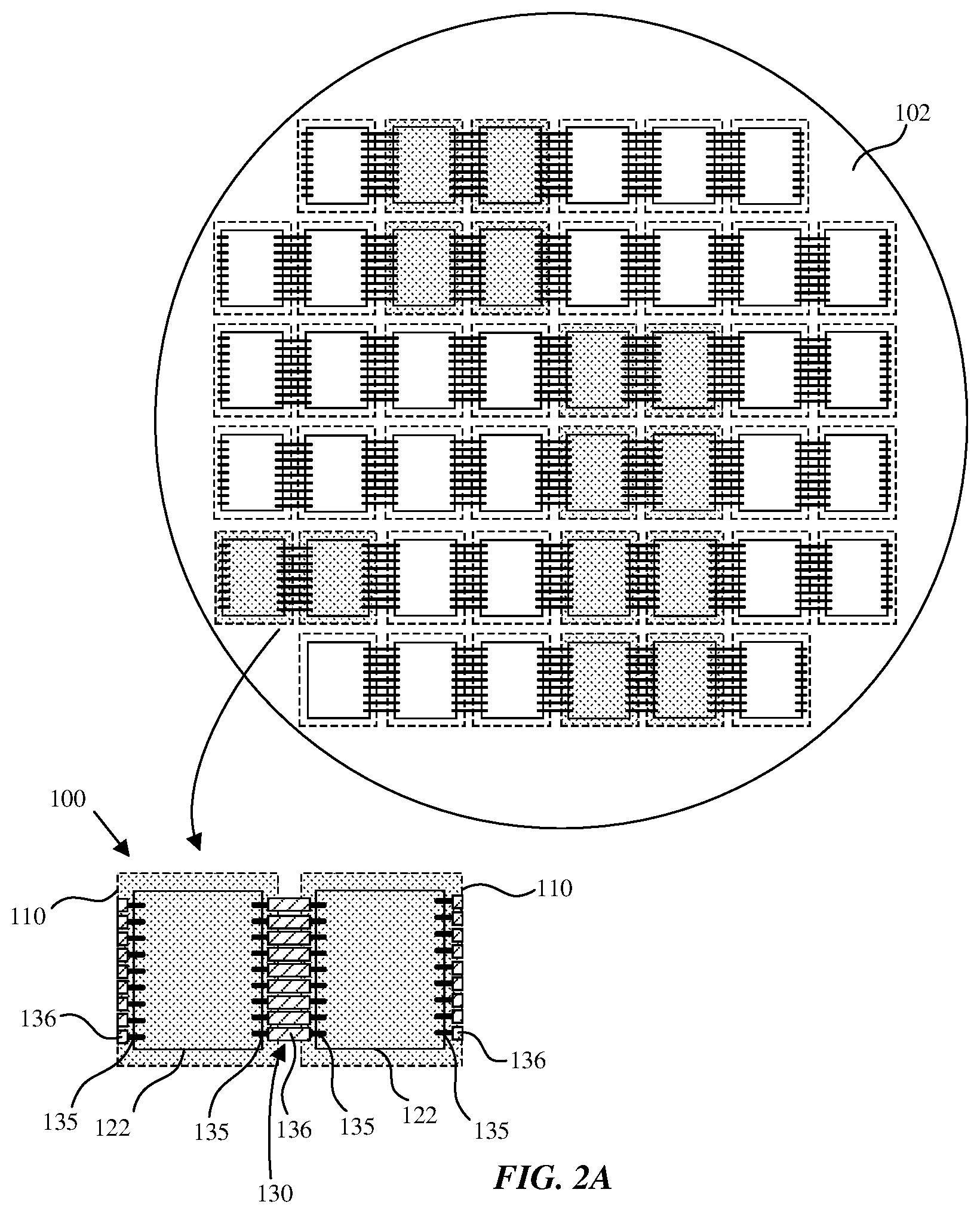
As The Hardcard states, Apple is building the wafers with interconnect between adjacent M1 Max dies, so the ones going in M1 Ultra are diced as a pair - at slightly larger than reticle size of 858 mm^2. So you some need some pretty damn good yields for this, since all M1 Ultras are sold with their full complement of CPU and GPU cores. See the figure from patent:

US20210217702A1-20210715-D00002.png


If you look at this picture, it implies the possibility that four dies could be carved out and all connected together. If 2.5 TB/sec is enough for four, maybe that's how they'll do it, though that's less efficient than my sandwich in terms of wire delay.

If that figure is showing stitches that are present but not used (i.e. those stitches would on the "top" of the M1 Max and may not be usable) then my sandwich idea may be the only feasible way of making this happen. From reading the patents and seeing how involved the steps are for CoWoS it doesn't seem too likely they'd sandwich them directly to both sides of a single interposer. Instead what I would expect is they'd build two M1 Ultra interposer packages, and connect those to some type of third structure. That's the patent we need to find, one that details connecting two CoWoS packages to two sides of something else.