Worklog: Project Thief - Fully Watercooled Dual PC

Page 6 - Seeking answers? Join the AnandTech community: where nearly half-a-million members share solutions and discuss the latest tech.

T_Yamamoto

Lifer
Jul 6, 2011
15,007
795
126
that looks like a huge ass case.
cant wait to see this sucker in action.

have you thought about like (i dont know if youve already decided) but one side is red and the other is blue

fire and ice :D
 

stren

Senior member
Jul 20, 2011
270
0
76
that looks like a huge ass case.
cant wait to see this sucker in action.

have you thought about like (i dont know if youve already decided) but one side is red and the other is blue

fire and ice :D

Haha there is a caselabs fire and ice build that someone did - I'll have to see if I can find it. Because both motherboards are rampage extremes, the red is going to be on both sides anyway :(

DAMN! this thing is Gianormous!

Hell yeah it's huge!
 

stren

Senior member
Jul 20, 2011
270
0
76
So the only thing I got done this week was changing the switch plate to one that matched the exterior color. Here's the original:

PhZt6h.jpg


The cover is held on with two nuts:

XGjMfh.jpg


Put the new one on:

B9cAmh.jpg


Reattach the switches:

Rt1bOh.jpg


Install it:

IBuaAh.jpg


And put the panels back one:

B91tEh.jpg


That's probably it for the next week at which point a large order of parts should be coming in :thumb:
 

Rubycon

Madame President
Aug 10, 2005
17,768
485
126
That form factor is large enough that if it had a single HTPX horizontal tray the bottom areas could be served by a pair of MORA3 9x140s. :cool:
 

stren

Senior member
Jul 20, 2011
270
0
76
Looking very fine cant wait to see the finished product and some benches :D

Yeah me too - I've had that 3930K for a month now and haven't powered it on yet!

Nice progress, I like how it looks now.

Thanks again general!

That form factor is large enough that if it had a single HTPX horizontal tray the bottom areas could be served by a pair of MORA3 9x140s. :cool:

Yeah it sounds like Jim is waiting for Merlin (smaller cases) to be done before the horizontal version. The horizontal one could fit 2 side mounted 140.9's I expect, plus a bottom mounted one, plus front mounted 560's lol.

Rubycon - did you ever do the big slappy mod on the EK res to use it with the Iwaki? If so I may have some questions, if not I may have to go register over at RRR
 

Rubycon

Madame President
Aug 10, 2005
17,768
485
126
Rubycon - did you ever do the big slappy mod on the EK res to use it with the Iwaki? If so I may have some questions, if not I may have to go register over at RRR

IIRC that's the one with the single tall res and uses a long radius electrical conduit (PVC) elbow leading to the pump?

Never worked with that, the system I have uses a manifold delivery system that sums up four large reservoirs (1 per MORA3) and and delivers it through a 3/4" ID pipe to the pump directly. Pressure sensors are used to balance the system since the radiators are in parallel and there's never an issue with reduced pressure at the pump volute. Most people would never notice even a severe pressure drop as in when cavitation begins it's already far too severe.

Additionally turbulence in the reservoir where an air-water interface occurs can prolong/enhance the effect of increased dissolved oxygen/carbon dioxide in the coolant. This in turn can have an oxidizing effect on certain parts (copper blocks and some fittings) where high flow/turbulence exists. This is the cause of the dark coloration in waterblocks under jet plates, for example.

No matter how cool it looks, bubbles and the so-called waterfall effect in tall vertical reservoirs are bad overall.

If wide temperature swings are possible it's also a good idea to install a relief valve on the system that's close to being filled up as well. If the system is filled to top with 18C water and water increases to over 34C (rather unlikely in a quad MORA3 based system on basis of thermal load only - sharp increase in ambient has to do it and has happened before!) the system could experience a severe spike in pressure that could possibly cause a blow out to occur. This is also why I dismiss acrylic topped blocks in said system.

One way to allow for "cushion" is to use vertical reservoirs with extended dip tubes. As long as the water level stays sufficiently higher than the bottom of the dip tube (input), potential gas exchange is minimized. Another option is to keep the open spaces in the reservoirs charged with an inert gas such as argon but this tends to drive the scope of the project beyond the level of the typical hobbyist. :)
 

stren

Senior member
Jul 20, 2011
270
0
76
IIRC that's the one with the single tall res and uses a long radius electrical conduit (PVC) elbow leading to the pump?

Never worked with that, the system I have uses a manifold delivery system that sums up four large reservoirs (1 per MORA3) and and delivers it through a 3/4" ID pipe to the pump directly. Pressure sensors are used to balance the system since the radiators are in parallel and there's never an issue with reduced pressure at the pump volute. Most people would never notice even a severe pressure drop as in when cavitation begins it's already far too severe.

Additionally turbulence in the reservoir where an air-water interface occurs can prolong/enhance the effect of increased dissolved oxygen/carbon dioxide in the coolant. This in turn can have an oxidizing effect on certain parts (copper blocks and some fittings) where high flow/turbulence exists. This is the cause of the dark coloration in waterblocks under jet plates, for example.

No matter how cool it looks, bubbles and the so-called waterfall effect in tall vertical reservoirs are bad overall.

If wide temperature swings are possible it's also a good idea to install a relief valve on the system that's close to being filled up as well. If the system is filled to top with 18C water and water increases to over 34C (rather unlikely in a quad MORA3 based system on basis of thermal load only - sharp increase in ambient has to do it and has happened before!) the system could experience a severe spike in pressure that could possibly cause a blow out to occur. This is also why I dismiss acrylic topped blocks in said system.

One way to allow for "cushion" is to use vertical reservoirs with extended dip tubes. As long as the water level stays sufficiently higher than the bottom of the dip tube (input), potential gas exchange is minimized. Another option is to keep the open spaces in the reservoirs charged with an inert gas such as argon but this tends to drive the scope of the project beyond the level of the typical hobbyist. :)

Thanks again rubycon!

Yeah the waterfall reservoirs are swift becoming aesthetic centerpieces that will not be connected to any functional loops :whiste:

Yes you're correct about the big slappy mod using the 3/4" conduit tapped into an upside down 400mm res. I'm intrigued by this dip idea. I already see some significant pressure shifts in my system with temperature, so I'd definitely like to take this factor out. I'm not quite sure what you mean with the dip tube. What is the input inputting and what is it connected to? I've seen some people use expandable balloon type things like an accordian before.
 

stren

Senior member
Jul 20, 2011
270
0
76
Alrighty the fedex guy came, so here's some unboxing action:

TS5anh.jpg


Woooh packing

hNe1uh.jpg


ZScUbh.jpg


AjqNeh.jpg


Opened some boxes - the front rad is an ex560 - not quite sure why this was the first 560 rad that XSPC made.

jUyech.jpg


Mora 140.9 revealed - way thicker than the EX of course

ZdMi3h.jpg


Can you say quick disconnects?

NrNiHh.jpg
 

Rubycon

Madame President
Aug 10, 2005
17,768
485
126
Wow that's a lot of QDCs. Prepare for some back pressure!

Dip tube refers to the inlet side of the res. On BP res' they use a small chromed pipe a few cm long. This is easy to extend by sliding a piece of 1/2" PEX over it making it the length you wish.

MORA3 140x9s also have roughly 90' of tubing for the water to run through so there is some restriction there too. You can see how important to have a real pump (RD30) is now...
 

stren

Senior member
Jul 20, 2011
270
0
76
Wow that's a lot of QDCs. Prepare for some back pressure!

Dip tube refers to the inlet side of the res. On BP res' they use a small chromed pipe a few cm long. This is easy to extend by sliding a piece of 1/2" PEX over it making it the length you wish.

MORA3 140x9s also have roughly 90' of tubing for the water to run through so there is some restriction there too. You can see how important to have a real pump (RD30) is now...

Yeah only 4 pairs are for the RD30 loop, then 2 pairs for the workstation cpu/mora only loop. They are the VL4Ns which are way less restrictive than any other QDCs Koolance make. I'm trying to get FTWPC to sell some RD-40's, if they do I may pick one up and run the RD30 on the workstation loop as you have told me so many times to run the mora with an rd30 lol.

BTW is there any problem running a rad immediately after the RD30?

Right now I was thinking rd30 -> 360 rad -> cpu -> 560 rad -> 3x480s -> 560 rad -> ek 400 res with big slappy mod

then for the other loop:

Dual PMP450s at 24V -> cpu -> mora3
 

Rubycon

Madame President
Aug 10, 2005
17,768
485
126
MORAs will handle it no problem at all. Our stuff is tested with over 50psig. The MORAs laugh at that!

RD30 at 18V is more powerful than a pair of D5 strong at 24V. (tested)

RD40 has outstanding pressure but be careful as many things used in PC watercooling simply cannot cope with these pressures.
 

stren

Senior member
Jul 20, 2011
270
0
76
What do you think about a hwlabs GTX360 being first in line from the RD30/40?
 

stren

Senior member
Jul 20, 2011
270
0
76
2nd update of the day:-

So I played around with my own version of the big slappy mod for the Iwaki - the idea is you tap the cylinder res for a much larger feed for the pump. The pump can't be on it's back so you need a nice slow 90 degree bend. The tough part is then getting down to the 5/8 OD pipe that is the inlet to the Iwaki. Here I used 1" pipe going to a 1/2" female converter fitted with a 5/8" brass barb. I butted the barb up right against the inlet and stretched some 0.5" tube over it:

XwlvOh.jpg


The feed may not be quite as good as the original big slappy as that only had a bout 3/4" of 5/8 inlet tube, vs this 2.5" on this version. However the downpipe is 1" instead of the 3/4" that was used. So hopefully the extra width balances it out a bit. Here's a photo of the original big slappy:

4270331234_ccd8bcfac4_o.jpg


and amuseme's version:

IMG_1608copy.jpg


We'll see I might change to what they did, I feel like it might have better performance.

Also started spray painting test colors on a dead GT. I made a quick spray booth:

P4B7Zh.jpg


SKTlWh.jpg


Done - there's some metallic flake in the paint, the color isn't quite as orange as the tube though:

punuJh.jpg


Reassembled (kinda)

goRMmh.jpg


ms7H2h.jpg


Then a final comparison with it mounted on the 120 rad (this rad is just for the motherboard block loop). The rad will be painted silver to match:

0y5Fnh.jpg


So what do you think? Are the colors close enough? Both are slightly off. I wonder if I can get a color match from the powder coat supplier. I think I'll look for a different red at the least tomorrow. The match does depend on the lighting though.
 

Rubycon

Madame President
Aug 10, 2005
17,768
485
126
There's more than one way to skin a cat. ;)
As for your previous question, it matters more what's AFTER the rad and thus producing extra back pressure. Blocks and fittings - if carelessly installed - are the weak spots for leaks or blow outs.

The RD30 runs risk of suction starvation on low restriction circuits. Of course this pump moves more at high restriction than most WC "hobbyist grade" pumps do with zero head! If you see cyclone/whirlpools in reservoirs the flow is too high for that particular res. Double up and plumb them into a common feed (manifold) of one size up, etc.

Painting rotors is risky. They are precisely balanced for a reason. Throw the balance off - even a little - and don't expect the bearings to last anywhere near their published mean time between failure (MTBF) ratings...

Here's a hint: with the fan running at full speed hold it by the frame. If it has a shimmy feel to it the balance is off too much.
 

stren

Senior member
Jul 20, 2011
270
0
76
There's more than one way to skin a cat. ;)
As for your previous question, it matters more what's AFTER the rad and thus producing extra back pressure. Blocks and fittings - if carelessly installed - are the weak spots for leaks or blow outs.

The RD30 runs risk of suction starvation on low restriction circuits. Of course this pump moves more at high restriction than most WC "hobbyist grade" pumps do with zero head! If you see cyclone/whirlpools in reservoirs the flow is too high for that particular res. Double up and plumb them into a common feed (manifold) of one size up, etc.

Painting rotors is risky. They are precisely balanced for a reason. Throw the balance off - even a little - and don't expect the bearings to last anywhere near their published mean time between failure (MTBF) ratings...

Here's a hint: with the fan running at full speed hold it by the frame. If it has a shimmy feel to it the balance is off too much.

So I guess I can try it with what I have, and see if there is a cyclone.

Haha yeah I was nervous about painting the rotor, I tried to do as thin and even coat as I could. Only the fans in the window will get painted, the rest of the rotors will be left alone :)
 

mnewsham

Lifer
Oct 2, 2010
14,539
428
136
Oh what I would give to have that sucker. I want it so badly :(

Looking good so far, really cant wait to see it all together.
 

stren

Senior member
Jul 20, 2011
270
0
76
Got some more today seeing as I got done with my deadline yesterday. I wanted to get the 120 rad painted to match the fan to see how it looks and what fittings to go with. So I started sanding down the brand new gt stealth:

ec0teh.jpg


Masked it off and applied primer:

aIDLlh.jpg


Then painted a matching cover to dress up the fan a little:

bRMFyh.jpg


While I was waiting for paint to dry, I put together the quick disconnect pairs, some will mount to panels with a g1/4 fitting on the other side, while some screw directly into radiators:

KU2A5h.jpg


Then I realized I need two more pairs...

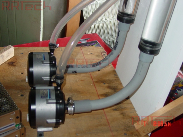
I also did some work on the pump mounting. I added a drain port to the inlet tube and mapped out the cuts I wanted to make to the base panel. Air has to flow through the base panel, so there has to be some cut outs. Because the pump will vibrate, I'm worried about making the noise worse with a floppy piece of metal, so I was thinking to stiffen it with two 1" by 1/4" steel bars screwed underneath the base plate (these are the two dark shaded strips. I'll have to add some rubber strips to try and isolate the baseplate from the frame also.

a6y3Xh.jpg


Here's a quick look at the painted rad from earlier with the fan on top:

1Lcwyh.jpg


And here's a piece of acrylic that was laser cut and then painted to match. The dimensions aren't quite right though:

yE8Uth.jpg


Not sure whether to do something like this or not. I don't think I should use the zerg symbol anyway as it doesn't match the theme, but it's fun to play around.

Originally I had wanted to paint all the fans, then I got lazy and thought, well I'm more likely to screw them up by painting them (imbalanced rotors and all), plus they won't be seen so who cares. So I took a look to see if I could justify lazy or not: Here are the stock typhoons showing:

R5T0jh.jpg


Here's one painted typhoon just rested up in there. Obviously the space around the fan (fan adapter) would be painted silver too so it would blend better. The red can't be seen too well though:

4ZOFzh.jpg


So I figure I have four options:

A) leave the GTs stock (lazy and quieter but looks ugly)
B) paint the GTs housing only and leave the rotor grey (quiet but stands out less
C) paint the GT fully (risks noise from a now unbalanced rotor and doesn't look much better than option b)
D) paint the GT fully and add some white LEDs to actually show the metallic red rotor off a little bit

What do you all think? I'm guessing rubycon will go with option A or at most B ;)
 

OVerLoRDI

Diamond Member
Jan 22, 2006
5,494
4
81
I'd go with B. The GT blades match the case color. Maybe paint the housing of the fans red?
 

Rubycon

Madame President
Aug 10, 2005
17,768
485
126
What do you all think? I'm guessing rubycon will go with option A or at most B ;)

I'm all about function so yes I'd say leave them alone. :p

That said, if you want to go all out here are some ideas for your fans.

Paint the hubs black. (Little chance of imbalance in the center of the rotors!) Then paint a pattern in a fluorescent paint/dye that shows up well when irradiated with near UV radiation of ~400 nanometers. This is close to the popular "blacklight blue" as seen in various venues, etc. Some ideas for the pattern could be similar to what they paint in the center hub of jet engines (spring) so you can see them turning.

For the exciter illumination use high power UV LEDs in the 390-410nm range. Drive them with a PWM circuit creating a stroboscopic effect where it makes your hub pattern seem to float nearly still. If the PWM is fairly stable this can also serve as an indicator that your fans are speeding up (filters clogged?) as the pattern starts to move faster, etc. Of course this requires a stable supply to the fans as well. (it would be far easier to use a fixed PWM on the LED and adjust the speed of the fans with a regulated driver)

In any case you wanted to know and there it is! :biggrin: