Question Will my old EVGA Supernova 750 G2 work with my new 870E motherboard?

catboy

Member
Oct 18, 2013
85
9
71
I have an old EVGA Supernova 750 G2 PSU that I bought in 2016 or 2017 and that I've only used for a few months back then, and then I got a new computer with a new PSU.

I am now building a new system, with an AsRock 870E Nova motherboard.

I am thinking of extracting that old EVGA 750 G2 PSU and using it to power my new 870E motherboard.

Can you tell me if that will work?

Is there any reason why I shouldn't do that? Or will it be totally fine and no problems will come up as a result of using such an old PSU with a new motherboard?

I'm using a 2080 GPU.

Another question I have is: how will I know what are all the cables that I need to attach from my PSU to my motherboard, in order to make all of the functions of my motherboard work?

In the past, I would pay a technician to install the motherboard into the case, and install the CPU and heatsink and PSU.

This time I am going to try to do those things myself.

I've looked at my motherboard's online manual prior to making this post, but after doing that, I still feel very uncertain about knowing which cables I will need to plug in, and where, in order to make my new system work fully & properly. And also I don't know how to make sure that I won't have any cables plugged into the wrong the spot, or not plugged in at all even when they should be.

What can I do to make sure I get all of this straightened out? I'd rather not have to guess about how to do this, but I don't feel like I have enough knowledge to be confident that I can do it properly.
 

yottabit

Golden Member
Jun 5, 2008
1,588
675
146
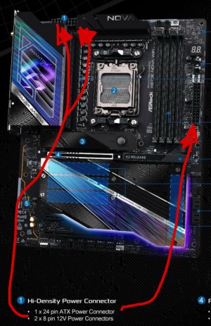
Looks like mobo has 1x 24 pin and 2x 8 pin CPU power connectors

PSU had 1x 24 pin and 2x 8 pin CPU power connectors

No problem. That being said I do like to replace PSU after ~10 years, but I wouldn’t be stressed about re-using it short term.


The cable connectors should be clearly labeled. Just don’t confuse a VGA 8 pin power connector with the CPU 8 pin power. They look similar but won’t fit.

I’d spend most of your effort researching how to seat the CPU and heatsink properly (which shouldn’t be much effort, just a couple YouTube videos) as that’s the area most people run into trouble if you’re going to run into trouble.

Basically: Unlock the latch and open the tray and remove the safety insert. Gently place CPU in paying attention that the marked corner aligns correctly with the socket. Close tray and latch it down. Apply a proper amount of thermal paste. Attach heatsink and clamp down.

Add GPU and memory and make sure they are firmly seated. Don’t forget to re-connect GPU power cables.

If you’re using just 2 DIMMs of RAM check the motherboard manual for which slots they should go into. There will be some preferred slots.

I recommend install CPU (with heatsink), RAM, GPU, and check that the system posts before doing much else. Some people do this outside the case on a safe workbench. I usually install in the case but leave off wires for front panel headers RGB lights etc, or connecting any drives until I prove it POSTs

Oh and when removing GPU from your current rig, be sure to press down the release lever on your current motherboard (after you remove the screw(s) holding the GPU to the case) to pop it free. DON’T just try to yank it out without actuating the release lever first. After removing your motherboard, pop your old motherboard I/O shield out and install the new one before installing the new motherboard. Make sure the standoffs are in the correct locations- if not you may need to shuffle them around.

The electrical connections are really the easiest part, they won’t fit into the wrong slot and I’ve never seen permanent damage if you forget to connect one, it just may not boot. The important thing is just to have a general mechanical aptitude for the amount of pressure you need to apply to seat things. It pretty much all fits like Lego pieces and is pretty hard to mess up but you don’t want to force something if it isn’t aligned properly.
 
Last edited:

catboy

Member
Oct 18, 2013
85
9
71
Thanks for the help, yottabit.

I will try to implement all the things you've mentioned.

Do I need to buy antistatic mat to build on?

I was thinking to skip doing that, and instead to put my motherboard box on the floor, and then put the motherboard's bag on top of the box on the floor, and then mount my CPU and heatsink while the motherboard is there.

My new case will be an Antec Flux Pro.

With the video tutorials for mounting the CPU cooler for that case that I've watched, they always use an AIO cooler, and they mount the CPU cooler after the motherboard has already been mounted into the case, and while the case is sitting upright in its normal position.

But most of the advice I've seen online says to do the opposite, and instead to mount the CPU cooler while the motherboard is outside of the case.

The cooler I'm using is a Noctua D15 G2.

As for the power connections that go into the motherboard: the aspects of that which I'm feeling especially iffy about are things like connecting the front panel connectors for the power button and reset button and HDD LED, and the connections to make all of the USB ports, and things like that, work.

I'm also confused because when I look at the photos of and manual for the Flux Pro, it doesn't seem to have any HDD LED, as far as I can tell? And if that is so, then how I am supposed to see whether or not my HDD is active? (I find this LED is very important during things like system slowdowns...when it can help me to determine whether my system has crashed or not).

Another thing I'm worried about, is that when I bought the motherboard, an employee of the merchant took it out of the box & bag, in order to do a "pin check" on the socket.

I don't think he grounded himself before he did that, though. Is he likely to have damaged my motherboard when he touched it without grounding himself first?
 

catboy

Member
Oct 18, 2013
85
9
71
Looks like mobo has 1x 24 pin and 2x 8 pin CPU power connectors

So now I finally have all my parts (or so I thought), and I tried to implement the stuff we talked about in this thread.

I think it doesn't actually work though.:(

Because with the "2x 8 pin CPU power connectors," on this old PSU, those cables are actually split, at the ends that connect into the motherboard CPU power connectors, into 2 x 4pin CPU power connectors.

And the plastic of the connectors that go into the motherboard has an edge that juts out at the side, which prevents me from being able to plug in both of the 2 x4 pin connectors immediately adjacent to each other, as they would need to be in order to occupy all eight of the holes on one of the motherboard's CPU power connectors.

So I guess I am forced to buy a new PSU?
 

In2Photos

Platinum Member
Mar 21, 2007
2,443
2,683
136
So now I finally have all my parts (or so I thought), and I tried to implement the stuff we talked about in this thread.

I think it doesn't actually work though.:(

Because with the "2x 8 pin CPU power connectors," on this old PSU, those cables are actually split, at the ends that connect into the motherboard CPU power connectors, into 2 x 4pin CPU power connectors.

And the plastic of the connectors that go into the motherboard has an edge that juts out at the side, which prevents me from being able to plug in both of the 2 x4 pin connectors immediately adjacent to each other, as they would need to be in order to occupy all eight of the holes on one of the motherboard's CPU power connectors.

So I guess I am forced to buy a new PSU?
The 2x4 pin will work just fine but you have to put the connector together in a way that they "combine" like a puzzle. Sometimes you can put the part of the connector in that doesn't have the clip, then insert the part that has the clip. On others you might have to put the 2 pieces together as you insert them into the motherboard.
 
  • Like
Reactions: Shmee

catboy

Member
Oct 18, 2013
85
9
71
The 2x4 pin will work just fine but you have to put the connector together in a way that they "combine" like a puzzle. Sometimes you can put the part of the connector in that doesn't have the clip, then insert the part that has the clip. On others you might have to put the 2 pieces together as you insert them into the motherboard.

Thank you for the feedback.

I think I finally figured it out.

On one side of the connectors, there is a jutting out edge where the plastic of the connectors says "CPU" on it. If I place those two labeled sides beside each other, then it creates a gap between the two sets of four pin connectors, which makes it impossible to put into the motherboard, because the motherboard's connector has no gap.

But after reading your post, I spent another half an hour trying to figure it out, and then I discovered that if I put the non-labeled sides together, then the gap is gone (but there is no way to snap them together on this particular cable).

So hopefully it will work after all. I'll test it out after I eat my dinner.

Your post saved me from assuming I needed to buy a new PSU to solve this problem, so thanks a lot for that.