Learnt electronics before, but never thought electricity is so complex and mind blowing.
==
1st video. The Big Misconception About Electricity
2nd video. How Electricity Actually Works
I think, we should see this similar to a transmissionline description and velocity factor. That wire still has inductance and when the switch switches on, the voltage will rise from 0V to battery level Vy. This will take time from t = 0 to t+x. During that time, a changing voltage is present and therefore a changing current. Dielectric constants and all that stuff will start to happen. Time domain reflection measurements are common. And this seems to fall in such a situation. Just see the lamp as bad impedance or proper impedance depending on the resistance of the lamp and the electrical characteristics of the cable like impedance. Therefore, light only moves at the speed of light in vacuum : c = 300 000 km /s. But electrical signals also. But in conductive materials also surrounded by non conductive materials but with dielectric behavior the speed of the electric signal is much lower than the speed of light. Hence the velocity factor correction calculation. So the statement is to be called : "special".
And from the hyperphysics site it is known that electrons flow at a low rate from one end of the wire to the other when dc current is applied. Think milliseconds to seconds. Depending on the length.

picwire.com
Excerpt :
"
In theory, electrical signals move at the speed of light. Cables only slow them down. The ratio of actual speed to the speed of light is known as the velocity factor, or Velocity of Propagation (VOP), expressed as a percentage of the speed of light in free space.
This slowing effect is almost entirely caused by the dielectric material; in coaxial cables, the insulation between the shield and the center conductor. For a closed-cell foam dielectric, for example, the VOP may approach 90%, meaning that a signal will travel at 90% of the speed of light. For solid Teflon®, the VOP is typically about 70%.
"

Excerpt :"
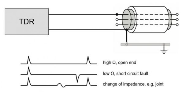
A TDR sends a low voltage pulse into the cable under test and at any impedance change within the cable a reflection will be seen. The TDR measures the time between release and return of the low voltage pulse from any reflections. By measuring the time and knowing the propagation velocity of the pulse, the distance to the reflection can be calculated. This helps to give a user information on the type of impedance change or failure that could be present in the cable.
The below image shows a typical set-up for a TDR measurement. A parallel path of two conductors is required to see a reflection graph of a pulse traveling along a cable. Therefore, one of the leads of the TDR is connected to one phase of the cable and the other lead is connected to the cable sheath, which is also connected to ground. The reflection of the pulse is caused by the change of impedance between those two paths and every interruption, change of impedance, or cable end is indicated. The low voltage pulse travels through the cable and is reflected positively at the cable end or at any cable interruption (cable cut). At a short circuit point this low voltage impulse is reflected negatively. A change of the impedance in the cable, such as with a joint, will be displayed as a laid S.
"
Understand the basics of Time Domain Reflectometry (TDR). Learn how TDR works to locate faults and assess cable integrity effectively.

www.hvtechnologies.com