- Feb 14, 2017
- 1
- 0
- 1
So here's what i have currently.
Mobo: Asus x99 Deluxe II
Case: Thermaltake W100 (P100 in future possibly)
CPU: intel i7 6900k OCd to 4.2ghz
CPU cooler: Corsair H100i GTX
GPUs: (2) EVGA GTX FTW ICXs (have the FTW Gaming ACX3 versions but trading up)
PSU: EVGA 1200w P2
RAM: 4 x 16gb Gskill 3200mhz (64gb total)
Fans Im looking at getting.
- 3 Air Flow Fans (3 front): Corsair AF120 (CO-9050004-WW) @ 1650rpm's at Power Draw (@ +12V): 0.13A
- 4 SP Fans ( EK 480 XE radiator TOP): Corsair SP120 (CO-9050012-WW) @ 1450rpm's at Power Draw (@ +12V): 0.08A
- 4 SP Fans ( EK 480 XE radiator BOTTOM): Corsair SP120 (CO-9050012-WW) @ 1450rpm's at Power Draw (@ +12V): 0.08A
- 1 Back Fan: Corsair AF120 (CO-9050004-WW) @ 1650rpm's at Power Draw (@ +12V): 0.13A
The mobo i have is the Asus deluxe II motherboard. Images below.
Click for Mobo Image 1
Click for Mobo Image 2
Click for Mobo Image 3
Click for Mobo Image 4
my board does come with this fan extension card as well.
Fan Extension Board
The pump/res combo im getting.
Click for Image of EK EXRES 140 Revo D5 pump/res combo
Radiators im getting are the EK 480 XE (60mm thick on top and probably either the 25mm or 45mm thick depending on what fits in the bottom p100 when i get it in future)
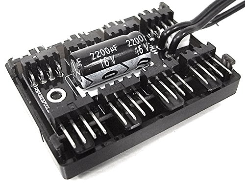
My question is this... Based on if you look at images of my fan header layout. If i do the (4) SP120 fans as listed above on both radiators (top for now till i get bottom in future), (3) of the AF120s in front and 1 of those in back of case and from the link above with pump/res combo that has not only a 4 pin molex power but the 4 pin PWM connector as well. I know the 4 fans on top can maybe go to one of the (click to view product -->) 4 pin pwm power distribution pcb 8-way block's and plug into the CPU_FAN connector but again as per the fan header image of my board where or how would i plug in the 4 case fans, bottom 4 rad fans and the two pwm connectors on the pumps?
I don't wanna plug to many things in the fan headers and overload the connection nor do i wanna plug the wrong things into them so i really really need help on how i should do this best.
I thought of getting some kind of 5 1/4" style fan controller for the front 5 1/4" bays if i can fit it in but i dont know if that would work nor do i know if it would control the fan speed automatically or do i have to do that manually and always keep control of the temps and adjust fan speed manually?
I also know that its not the number of fans that determine positive air pressure in case but the fan speed of the fans in front sucking more in than the whats going out the exhaust fans.
Last edited:


