I think you misunderstand what the metal shim is for, understandable because the posts have been going up in rapid succession.
The shim is to lift the IHS off of the PCB such that the resulting gap between the underside of the IHS and the CPU silicon die is the same gap hieght as existed when the original stock CPU TIM was in place.
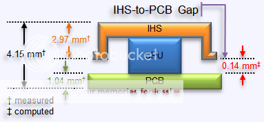
^ right now I have the situation on the right, I want the situation on the left, I aim to accomplish that by shimming the IHS off of the PCB.
To do that my shim must first of all be thick enough to fill the current gap between the IHS and the PCB - that gap is 0.14mm.
I need the shim to further lift the IHS another 0.06mm so that the gap between the IHS and the CPU is then 0.06mm, the same as was present when the original TIM was present.
Then and only then can I test a CPU TIM replacement, such as NT-H1, and generate temperature data that is apples-to-apples comparable to the temperature generated with the stock Intel CPU TIM.
At this point in time, for all I know the 20°C improvement I observed is because I decreased the gap between the IHS and the CPU by 0.06mm versus the improvement coming from the replacement of the original CPU TIM.
We all suspect (assume) the TIM is the culprit, but it may just be that it is the gap itself that is the culprit for the elevated temps with a stock IB...and naturally we are right to assume the answer will be that it is partly the fault of both.
It seems implausible that Intel went to all the expense of using a "boutique" TIM like NT-H1 or MX-4 given that they don't bother to do it for their stock HSF TIM either, so it seems plausible to assume the stock CPU TIM is inferior to boutique TIMs.
At the same time a gap of 0.06mm is huge, that is a lot of TIM to shuffle the heat through. Reducing that gap by 50% or 75% will bring large improvements to the thermal conductivity of the stack, that's just basic heat transfer mechanics there.
So I want to shim the IHS, and I don't want a ductile metal like copper which will compress and bend under applied downforce. I wanted a high-carbon steel that would stand the best chance of retaining its physical dimensionality when compressed.
I think it will become a lot more clear what I am attempting to accomplish with the shim once I have the material in hand and can post some pics of the shim in place.