Combining particulate filter with a fan

dazednotconfused

Junior Member
Jul 18, 2020
8
0
6
This isn't a computer cooling question, but hopefully someone here with airflow knowledge can answer it.

I'm trying to pull filtered air through a small chamber as part of a lab experiment and getting unexpected results.

The chamber is a 12" long tube with 4" inside diameter. On one end is a particulate filter and on the other end is a 60mm fan. The desired effect is that the fan would pull the air though the filter and into the chamber and out on the fan side.

Instead, it doesn't seem to be pulling any air through the filter and the exhaust side of the fan seems to be both pulling air both in and out at the same time.

I've tried a fan rated at 13.8 CFM and another at 17.2 CFM and neither is pulling air through the filter.

The filter is cannibalized from a face mask, so I wouldn't think it would be much resistance.

Any suggestions?

Moved to ask a professional forum.

AT Mod Usandthem
 
Last edited by a moderator:

dazednotconfused

Junior Member
Jul 18, 2020
8
0
6
You might want to try adding a 4" ID x 6"long tube to the fan exhaust.

Thanks for the reply. I tried that now. It made a slight improvement, but still hardly any air coming through the filter end and on the fan exhaust end lots of turbulence (air going in and out). Maybe a 17 CFM fan is still under powered?
 

mindless1

Diamond Member
Aug 11, 2001
8,058
1,444
126
Does your exhaust fan have an air-tight seal between the frame and tube? This is fairly important to achieve good efficiency, but axial fans are very poor at maintaining static pressure (or in this case vac) which is the more important parameter for your use, though they do improve a bit, the thicker they are.

It is hard to predict the flow rate, depending on size and type of fan, and RPM, and the filter impedance, but I would shoot for a larger fan, say 92mm x 25mm, and a medium RPM range that you throttle back if you decide you want to sacrifice some flow for noise reduction.

However, if you can sacrifice noise for flow increase, then you want a different type of fan, which some call a squirrel cage blower but is more properly called a radial or centrifugal fan. If you're on a tight budget you can scavenge the offerings at electronics surplus sites, but if you have a large budget, there are many to choose from at electronics supply houses like Digikey, Mouser et al depending on your regional location.
 
Last edited:

dazednotconfused

Junior Member
Jul 18, 2020
8
0
6
Does your exhaust fan have an air-tight seal between the frame and tube? This is fairly important to achieve good efficiency, but axial fans are very poor at maintaining static pressure (or in this case vac), though they do improve a bit, the thicker they are.

It is hard to predict the flow rate, depending on size and type of fan, and RPM, and the filter impedance, but I would shoot for a larger fan, say 92mm x 25mm, and a medium RPM range that you throttle back if you decide you want to sacrifice some flow for noise reduction.

However, if you can sacrifice noise for flow increase, then you want a different type of fan, which some call a squirrel cage blower but is more properly called a radial or centrifugal fan. If you're on a tight budget you can scavenge the offerings at electronics surplus sites, but if you have a large budget, there are many to choose from at electronics supply houses like Digikey, Mouser et al depending on your regional location.

That's extremely helpful. Yes, in the axial fans we are testing there is a gap between the blades and the fan tube which presumably is how the air was flowing backwards through.

Will switch to a blower fan per your suggestion. Thanks!
 

herm0016

Diamond Member
Feb 26, 2005
8,393
1,026
126
think about how you are creating a pressure differential instead of how you are moving air, you will be creating a low pressure in the tube. axial fans are good at moving air but very bad at creating pressure differentials.
 

Paperdoc

Platinum Member
Aug 17, 2006
2,307
278
126
The root of this may be the fans you tried were under-sized and under-designed.

A fan blade system can be designed to produce max air flow with almost NO resistance to flow (often quantified as backpressure), or to produce pretty good flow (not max) despite some backpressure. In your case, the "backpressure" is the resistance to air flow provided by the filter on the fan intake.

Any fan's output in terms of air flow is reduced by the resistance to air flow due to items in the flow path. In computer cases, those items might include wires and mobo components, fan intake dust filters, the fins of a heat exchanger portion of an CPU cooler system, the fins of a radiator in an AIO liquid cooling system, etc. Fan specs include values for Air Flow and Pressure. For a fan operating at its full speed, if you sketch a graph of air flow versus backpressure, VERY roughly it is a straight line starting at the spec'd max air flow for ZERO backpressure (flow resistance), and descending to ZERO Air Flow at and above the spec'd Pressure. In your case, no doubt, the flow resistance (backpresure) is significant. Your filter is something for particulates cannibalized from a face mask. That leaves a LOT of info missing. A really good filter such as that will have VERY fine pores and cause significant pressure drop across the filter for any air flow. Moreover, IF this was a filter from a USED mask, that item works by becoming more and more plugged up as particles are collected, so its resistance to air flow increases with use.

Bottom line, yes, you need a much more powerful fan, and perhaps one designed for higher backpressures when in use. Alternatively, if your experiment allows, you could use a much simpler and cheaper particulate filter with much larger pores that offers less air flow resistance.
 

sdifox

No Lifer
Sep 30, 2005
95,015
15,129
126
How clean do you need the air and how many cfm do you need?
 

mindless1

Diamond Member
Aug 11, 2001
8,058
1,444
126
heh, hold on while I jump in my time machine to go back and tell you not to get a PWM fan unless you need to control speed via PWM.

Some PWM fans need 5V on the PWM wire. You could try using a regulator or resistor divider to get 5V from 12V or do a web search for 555 PWM controller.

Edit: After looking at the datasheet, the above is incorrect (inapplicable to this particular fan). It needs a 100Hz PWM signal between 5V and 16V, with a duty cycle between 6% (min RPM) to 94% (max) and will not run outside this range.
 
Last edited:

dazednotconfused

Junior Member
Jul 18, 2020
8
0
6
Spec sheet says you have to use pwm.

Thanks for the reply. Earlier, both a 3-wire and a 4-wire Delta fan I tested worked with only red & black connected so I presumed the BFB0712HHD77 would too:


If the BFB0712HHD77 is different, is there a simple way (e.g. off the shelf solution) to get it to work without a motherboard? It has the static pressure and CFM most suited for this project and so I prefer to use it, but electronics is well outside my domain.

Thanks.
 

sdifox

No Lifer
Sep 30, 2005
95,015
15,129
126
Thanks for the reply. Earlier, both a 3-wire and a 4-wire Delta fan I tested worked with only red & black connected so I presumed the BFB0712HHD77 would too:


If the BFB0712HHD77 is different, is there a simple way (e.g. off the shelf solution) to get it to work without a motherboard? It has the static pressure and CFM most suited for this project and so I prefer to use it, but electronics is well outside my domain.

Thanks.

then get a different fan, since generating that PWM is not exactly easy. don't you have to run your experiment with PC anyway? If so just run a long 3 pin extender cable.
 

herm0016

Diamond Member
Feb 26, 2005
8,393
1,026
126
read page 6 of your spec sheet. also, if you can open it up, you should be able to just wire 12v to the fan motor itself and run it flat out.
 

dazednotconfused

Junior Member
Jul 18, 2020
8
0
6
then get a different fan, since generating that PWM is not exactly easy. don't you have to run your experiment with PC anyway? If so just run a long 3 pin extender cable.

It's an experiment that might turn into a standalone product that wouldn't use a PC. Not easy finding a fan with comparable CFM, static pressure, size, and decibel specs. Others tend be either too large or too loud.
 

mindless1

Diamond Member
Aug 11, 2001
8,058
1,444
126
If the BFB0712HHD77 is different, is there a simple way (e.g. off the shelf solution) to get it to work without a motherboard? It has the static pressure and CFM most suited for this project and so I prefer to use it, but electronics is well outside my domain.

Thanks.

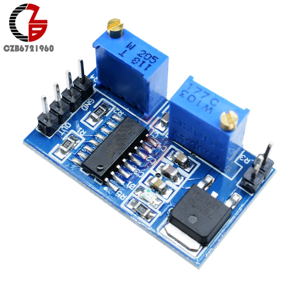
A typical, inexpensive SG3525 based controller module would appear to meet the requirements, then you'd adjust the onboard potentiometers to minimum (~100Hz) frequency and max(? up to 94%, too high and it stops spinning) duty cycle.


There are many other sellers, Aliexpress, Banggood, ebay, etc that are cheaper direct from China but with a month or more shipping wait.

You'd just feed it the same 12V in, then "out" to the PWM wire and common ground.
"onboard two precision adjustable resistors, R3 controls the duty cycle, R4 control frequency "

If your product is going to be made in significant quantities then you might want to just have a board developed without the potentiometers and instead resistors set to a fixed value, though unless it's a huge quantity it won't be cheaper to build yourself than buying bulk pre-made modules from China.


I can't guarantee this diagram is correct but the following site supplies it for a module that looks identical.


I'm only assuming this outputs a voltage relative to the input voltage instead of the 5V from the onboard regulator which is cutting it close to the minimum PWM voltage. Some board modification "might" (probably not) be needed but so far this is as close to off the shelf as I've found.

The mod I'm thinking of is that if the 5V regulator (78M05) is in series with everything else, and the SG3525 chip uses internal transistor switching, then there's going to be a forward voltage drop across that transistor. If that is the case, you'd either jumper out the regulator and feed it a relatively clean voltage closer to 6V, or another option is see the following LM7805 datasheet page 23, "Figure 12. Circuit for Increasing Output Voltage", or there are other methods,


I may be going too far down a rabbit hole and it'll work fine as-is, considering Delta is only spec'ing a guaranteed minimum while the true minimum may be below 5.0V
 
Last edited:

dazednotconfused

Junior Member
Jul 18, 2020
8
0
6
An typical, inexpensive SG3525 based controller module would appear to meet the requirements, then you'd adjust the onboard potentiometers to minimum (~100Hz) frequency and max(? up to 94%, too high and it stops spinning) duty cycle.


There are many other sellers, Aliexpress, Banggood, ebay, etc that are cheaper direct from China but with a month or more shipping wait.

You'd just feed it the same 12V in, then "out" to the PWM wire and common ground.
"onboard two precision adjustable resistors, R3 controls the duty cycle, R4 control frequency "

If your product is going to be made in significant quantities then you might want to just have a board developed without the potentiometers and instead resistors set to a fixed value, though unless it's a huge quantity it won't be cheaper to build yourself than buying bulk pre-made modules from China.


I can't guarantee this diagram is correct but the following site supplies it for a module that looks identical.


I'm only assuming this outputs a voltage relative to the input voltage instead of the 5V from the onboard regulator which is cutting it close to the minimum PWM voltage. Some board modification "might" (probably not) be needed but so far this is as close to off the shelf as I've found.

The mod I'm thinking of is that if the 5V regulator (78M05) is in series with everything else, and the SG3525 chip uses internal transistor switching, then there's going to be a forward voltage drop across that transistor. If that is the case, you'd either jumper out the regulator and feed it a relatively clean voltage closer to 6V, or another option is see the following LM7805 datasheet page 23, "Figure 12. Circuit for Increasing Output Voltage", or there are other methods,


I may be going too far down a rabbit hole and it'll work fine as-is, considering Delta is only spec'ing a guaranteed minimum while the true minimum may be below 5.0V

Many thanks for the detailed reply. Ordered it from Amazon and will test as soon as it arrives. Thanks.