Anyone here good at reading electrical schematics?

purbeast0

No Lifer
Sep 13, 2001
52,834
5,713
126
I am working on a project where I convert my Time Crisis into a JAMMA game by creating a harness.

Basically I am trying to make this. I already have all the connectors needed.

9D5HlBI.jpg


Here is the wiring schematics.

9FxcqNO.jpg


In the picture on the top, here is an explanation of each of those boards and their names that are on the schematics

1. top board ziptied to sticky things - gun drive pcb
2. 4 pin connector going to the very top edge is another board - joint pcb
3. board below the gun drive board - amp pcb
4. board at the very bottom with the most connectors to it - system super22 mother pcb
5. board on the right side with the wires all going to it - jamma fingerboard

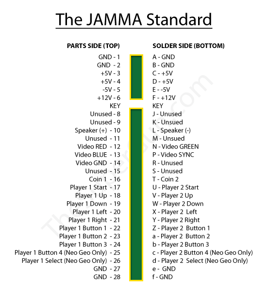
And the JAMMA pinout is here:

jamma_pinout.png


I am just wondering if someone can help a bit with those schematics. It is a bit more than I can seem to grasp at this point. Maybe I need to just sit down and try to follow it a bit more. I know that some wires go between the boards and some go to the JAMMA fingerboard.

Any pointers on how to read it a bit better and do this? Thanks.

EDIT:

I think I'm starting to pick up a bit more on it.

Some of the labels like J2 for instance on the Mother PC Board section says "E1_12P" and I'm thinking that means "edge connector 12 pins" and there is a matching connector like that. However it's not labeled J2, it's labeled J6, but there is no J6 on the Mother PC Board part of the diagram so I am guessing I am looking at the right one.

Then I noticed all of the other E1_xP or just xP ones seem to match perfectly with what is on the Mother PC Board as well.

Another one I noticed is on the Amp PC Board, the J31 4P is the speakers. Well on the Amp PC Board, there is a 4 pin plug that is clearly the speaker one because it shows SP1-, SP1+, SP2-, SP2+. However again the J number is mismatched - on the actual Amp PC Board it is labeled J2.

So maybe the J labels simply aren't always identical, but the rest of them are?

EDIT 2:

Oh snap so someone gave me the link to the 50" Time Crisis manual and it has the schematics at the end and it appears to have the labels mine has - so perhaps this came from the 50" cabinet versus the 25" cabinet. The schematics are upside down though so I'll have to figure out how to flip a PDF upside down lol.


EDIT 3:

Here is the rotated schematic. I think I can actually follow this now that things match up, although it's a bit tougher to read.

aN00FiS.jpg
 
Last edited:

Scarpozzi

Lifer
Jun 13, 2000
26,389
1,777
126
I'm decent at reading them. My dad is much better. The trick is to start at the power end of the circuit and just go through it. Generate a parts list and draw the circuit (not paths) so you can picture a more physical view by knowing what chips /boards you're working with. If you can print a copy of the schematic, mark it up and circle things to break it down.

Reading a schematic to troubleshoot problems is a lot different than building the circuit from scratch....this, draw it out.
 

purbeast0

No Lifer
Sep 13, 2001
52,834
5,713
126
I'm decent at reading them. My dad is much better. The trick is to start at the power end of the circuit and just go through it. Generate a parts list and draw the circuit (not paths) so you can picture a more physical view by knowing what chips /boards you're working with. If you can print a copy of the schematic, mark it up and circle things to break it down.

Reading a schematic to troubleshoot problems is a lot different than building the circuit from scratch....this, draw it out.
Well I already have all of the parts. It's literally just going from the schematic that I posted (the last one which is the exact kit I have) to the JAMMA pinout. It doesn't use all of the JAMMA pinout at all, but in the schematics you will see things that go like to GND, +12v, +5v, etc. Eventually I will have to get one of those to the JAMMA harness. Same with the speakers, P1 start button, etc. And then I will have to make a gun harness that goes from the gun input to my gun.

I actually think I know what to do now after messing it a bit today.

I did realize today though that I got male pins for the mini molex connectors I have instead of female pins, which has now set me back. I ordered them from digikey today but it will not arrive for a few days. Sucks cause I had some time this afternoon. I started working on a few of the other connectors I have though that I had pins for, since there are multiple types.
 

Scarpozzi

Lifer
Jun 13, 2000
26,389
1,777
126
Well I already have all of the parts. It's literally just going from the schematic that I posted (the last one which is the exact kit I have) to the JAMMA pinout. It doesn't use all of the JAMMA pinout at all, but in the schematics you will see things that go like to GND, +12v, +5v, etc. Eventually I will have to get one of those to the JAMMA harness. Same with the speakers, P1 start button, etc. And then I will have to make a gun harness that goes from the gun input to my gun.

I actually think I know what to do now after messing it a bit today.

I did realize today though that I got male pins for the mini molex connectors I have instead of female pins, which has now set me back. I ordered them from digikey today but it will not arrive for a few days. Sucks cause I had some time this afternoon. I started working on a few of the other connectors I have though that I had pins for, since there are multiple types.
I was struggling to view the images on my phone earlier (not sure what was up). Those wiring diagrams aren't really the same as old-school schematics. I wasn't quite sure what you were trying to accomplish, but I looked up JAMMA and I get it now.

Seen this?


purbeast0

No Lifer
Sep 13, 2001
52,834
5,713
126
I was struggling to view the images on my phone earlier (not sure what was up). Those wiring diagrams aren't really the same as old-school schematics. I wasn't quite sure what you were trying to accomplish, but I looked up JAMMA and I get it now.

Seen this?

That is where the first schematic came from, it's in his description.
 

purbeast0

No Lifer
Sep 13, 2001
52,834
5,713
126
Made a little bit of progress this morning since there are different connectors and I had the correct pins for those.

I put a new fan on (12V) and ripped off the connector and put my own on there so I could run that to the fingerboard too. The other 9 pin large adapter is strictly power. It's got 3 +5v wires, 4 GND, and 1 +12v wire.

The fan is just +12v and GND. I ran out of black 18awg wire so had to use blue for the ground on there.

zBcqFoX.jpg
 
  • Like
Reactions: Scarpozzi

Scarpozzi

Lifer
Jun 13, 2000
26,389
1,777
126
I'm really good at reading electrical schematics, I just don't understand them.
That reminds me of The New Bob Newhart Show in Vermont. His handyman George said something like, "You're hvac system needs to be totally replaced. I'd explain it, but it's pretty difficult to understand." Newhart replied, "I'm pretty good with stuff like that, try me." Then he replied, "No. I mean, it's too difficult for me to understand."
 

purbeast0

No Lifer
Sep 13, 2001
52,834
5,713
126
Okay so I'm bumping this up because I have some specific questions about the pedal.

If you look on the bottom right, you see the PEDAL ASSY part. To the left of that you see the GUN DRIVE PCB.

I'm currently trying to get the pedal to register.

The PEDAL ASSY shows 3 wires - START1, GND, and then the awg15 green wire.

I have wired up START1 and GND from the PEDAL ASSY to the JAMMA harness START1 and GND. I know 100% the microswitch works because I have tested it at the JAMMA harness.

My question is about that 3rd AWG15 green wire.

Now inside of the pedal, that green wire is just screwed down to a terminal inside of the pedal.

And if I follow it in the schematics, it looks like it goes a screw down terminal in the SOLENOID ASSY on the GUN ASSY. It also looks to go to a screw down terminal on the GENERAL OVERSEAS CORD BOX ASSY.

The thing is, I don't have either the GUN ASSY because I'm using a different gun, or that GENERAL OVERSEAS CORD BOX ASSY, because that is something else I don't need.

Now my question is - what is this actually for? Is it just grounding the wire to the steel frame of the pedal? And that is different than the GND wire that is also on the pedeal?

There are a couple screw down terminals on the PCB RACK ASSY that is on the schematic, which is basically the big "case" everything is housed in, and it's metal. And if you look on the left side of the schematics, you can see the FAN MOTOR has a green AWG15 wire, and that is screwed to the frame.

So if I were to wire up that AWG15 from the PEDAL ASSY and run it to the screw down terminal on the PCB RACK ASSY, could that possibly make the pedal actually work?

I am just a bit confused as to why the pedal isn't working even though the switch clearly is. But I am not sure if I am missing something or not because I'm a noob to this.
 

VashHT

Diamond Member
Feb 1, 2007
3,058
865
136
That green cable looks like a safety GND that would be connected to chassis . Maybe possible it would cause problems if they are looking for some connection between the gun and the pedal through the chassis.

EDIT: to add, in systems I've worked on this kind of connection is really only for safety, they're there in case high voltage gets applied to different parts of the machine, they have to have a strong ground connection to the frame to direct it to ground.
 
Last edited: