- Sep 13, 2001
- 53,681
- 6,564
- 126
I am working on a project where I convert my Time Crisis into a JAMMA game by creating a harness.
Basically I am trying to make this. I already have all the connectors needed.

Here is the wiring schematics.

In the picture on the top, here is an explanation of each of those boards and their names that are on the schematics
1. top board ziptied to sticky things - gun drive pcb
2. 4 pin connector going to the very top edge is another board - joint pcb
3. board below the gun drive board - amp pcb
4. board at the very bottom with the most connectors to it - system super22 mother pcb
5. board on the right side with the wires all going to it - jamma fingerboard
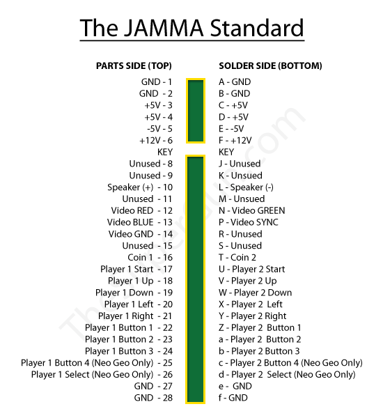
And the JAMMA pinout is here:

I am just wondering if someone can help a bit with those schematics. It is a bit more than I can seem to grasp at this point. Maybe I need to just sit down and try to follow it a bit more. I know that some wires go between the boards and some go to the JAMMA fingerboard.
Any pointers on how to read it a bit better and do this? Thanks.
EDIT:
I think I'm starting to pick up a bit more on it.
Some of the labels like J2 for instance on the Mother PC Board section says "E1_12P" and I'm thinking that means "edge connector 12 pins" and there is a matching connector like that. However it's not labeled J2, it's labeled J6, but there is no J6 on the Mother PC Board part of the diagram so I am guessing I am looking at the right one.
Then I noticed all of the other E1_xP or just xP ones seem to match perfectly with what is on the Mother PC Board as well.
Another one I noticed is on the Amp PC Board, the J31 4P is the speakers. Well on the Amp PC Board, there is a 4 pin plug that is clearly the speaker one because it shows SP1-, SP1+, SP2-, SP2+. However again the J number is mismatched - on the actual Amp PC Board it is labeled J2.
So maybe the J labels simply aren't always identical, but the rest of them are?
EDIT 2:
Oh snap so someone gave me the link to the 50" Time Crisis manual and it has the schematics at the end and it appears to have the labels mine has - so perhaps this came from the 50" cabinet versus the 25" cabinet. The schematics are upside down though so I'll have to figure out how to flip a PDF upside down lol.
EDIT 3:
Here is the rotated schematic. I think I can actually follow this now that things match up, although it's a bit tougher to read.

Basically I am trying to make this. I already have all the connectors needed.

Here is the wiring schematics.

In the picture on the top, here is an explanation of each of those boards and their names that are on the schematics
1. top board ziptied to sticky things - gun drive pcb
2. 4 pin connector going to the very top edge is another board - joint pcb
3. board below the gun drive board - amp pcb
4. board at the very bottom with the most connectors to it - system super22 mother pcb
5. board on the right side with the wires all going to it - jamma fingerboard
And the JAMMA pinout is here:

I am just wondering if someone can help a bit with those schematics. It is a bit more than I can seem to grasp at this point. Maybe I need to just sit down and try to follow it a bit more. I know that some wires go between the boards and some go to the JAMMA fingerboard.
Any pointers on how to read it a bit better and do this? Thanks.
EDIT:
I think I'm starting to pick up a bit more on it.
Some of the labels like J2 for instance on the Mother PC Board section says "E1_12P" and I'm thinking that means "edge connector 12 pins" and there is a matching connector like that. However it's not labeled J2, it's labeled J6, but there is no J6 on the Mother PC Board part of the diagram so I am guessing I am looking at the right one.
Then I noticed all of the other E1_xP or just xP ones seem to match perfectly with what is on the Mother PC Board as well.
Another one I noticed is on the Amp PC Board, the J31 4P is the speakers. Well on the Amp PC Board, there is a 4 pin plug that is clearly the speaker one because it shows SP1-, SP1+, SP2-, SP2+. However again the J number is mismatched - on the actual Amp PC Board it is labeled J2.
So maybe the J labels simply aren't always identical, but the rest of them are?
EDIT 2:
Oh snap so someone gave me the link to the 50" Time Crisis manual and it has the schematics at the end and it appears to have the labels mine has - so perhaps this came from the 50" cabinet versus the 25" cabinet. The schematics are upside down though so I'll have to figure out how to flip a PDF upside down lol.
EDIT 3:
Here is the rotated schematic. I think I can actually follow this now that things match up, although it's a bit tougher to read.

Last edited:


